P.S….shorter blog this time but longer video demo at the end of the post…….
In Part 1, we got to the point where we configured and manually kicked off a ‘Protection Job’. Next up we want to see how to recover from what we will call an orchestrated ‘mishap’ versus a disaster per se. We will cover off a inter cluster level recovery in a future post, whereby we actually lose our entire OpenShift cluster for whatever reason. For now though we are going to see what happens when we introduce some human error!
As per the diagram above we have our Namespace or ‘Project’ on OpenShift with our application Pod running inside, creatively named ‘ppdm-test-pod’.
Of course I have been busy developing my application and I have written a file to the mounted volume, which is backed via PowerStore. We will see this in more detail in the video demo, when we we run through the process end to end. This will serve as a simple example of data persistence post recovery.
Navigating back to the Pod details in the GUI we can verify the mount path for the storage volume and the associated Persistent Volume Claim (PVC). This is the one we attached in the last post ‘ppdm-claim-1’. Note: the path ‘mnt/storage’ is where we have written our demo text file.
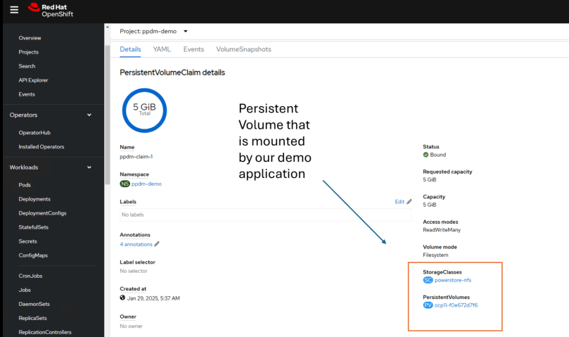
Delving a little deeper into the PVC details we can see the name of the Persistent Volume that has been created on PowerStore and the associated Storage Class.
Moving on over to PowerStore we can see that the ‘PersistentVolume’ ‘ocp11-f0e672d7f6’ is present as expected.
Orchestrated Failure
Before we orchestrate or demo a failure by deleting the OpenShift project, let’s ensure we have a copy on PPDM from which to recover. We did this in the last post, but just to confirm.
Next let’s go ahead and delete the namespace/project by navigating to the project and using the GUI to ‘Delete Project’.
Confirm ‘Delete Project’ when prompted.
Wait for a couple of minutes as the the namespace/project deletes and its associated entities take a couple of minutes to terminate and clear down.
No OpenShift project means our POD/Application has also been deleted as has our Persistent Volume Claim (PVC) and Persistent Volume. Note ‘ocp11-f0e672d7f6’ has disappeared.
What about on PowerStore itself. We can see here it is also gone! Where once we had 8 volumes present we now have 7. The CSI API has unbound the claim on the volume and Powerstore has deleted ‘ocp11-f0e672d7f6’.
Net result everything is gone, the Project/Namespace, the PVC, the volume on PowerStore and by definition our application. A bit of a mini disaster if you deleted the namespace in error…. it happens to the best of us!
Have no fear… PPDM and DDVE to the rescue.
Policy Driven Recovery via PPDM
Of course we have everything backed up in our DDVE instance, fully orchestrated by PPDM. Let’s head back over to the PPDM console and perform a full recovery.
Navigate to the ‘Restore’ menu and then to ‘Assets’.
The process is really very straightforward. Note you are presented with the option to recover from multiple point in time copies of the data (dependent on the length of your retention policy). I want to recover the latest copy. Select the namespace to recover and then click ‘Restore’.
Run through the menu. We will restore to the original cluster (In an upcoming blog we will restore to an alternate OpenShift Cluster on different hardware).
We will chose to restore everything, including cluster scoped resources, such as role bindings and custom resource definitions (CRD’s).
For the restore type we will ‘Restore to a New Namespace’, giving it the name of ‘ppdm-restored’.
We have only a copy of a single PVC to restore, so we will select that copy. Click ‘Next’.
Skipping through a couple of screenshots until we get to the last step ( Everything will be covered in the video demo). Make sure everything looks o.k. and then click ‘Restore’.
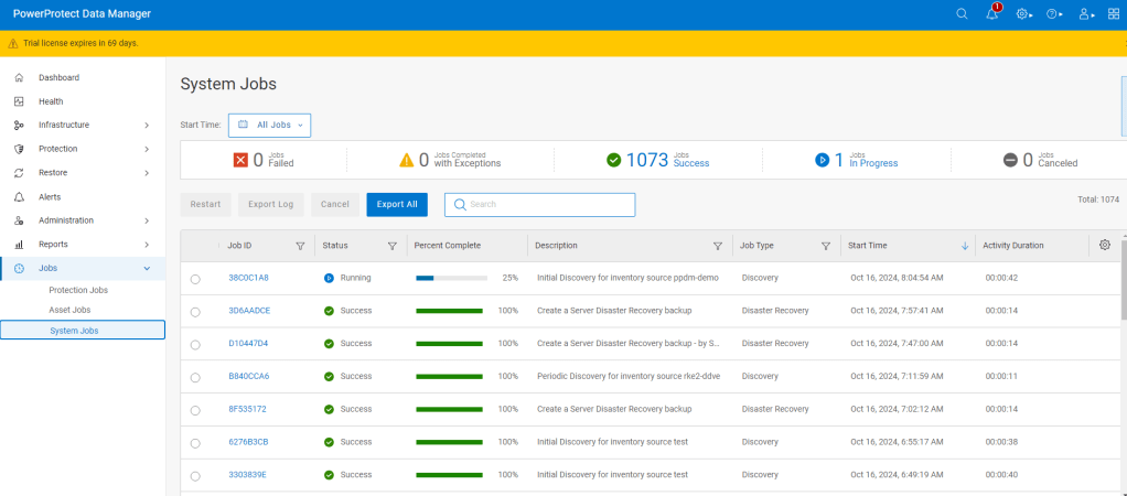
Navigate over to the jobs pane and monitor the status of the restore.
You can drill a little deeper into the Job to monitor its progress. There is a bit going on behind the scenes in terms of the cproxy pod deployment, so be patient. (this process will be the subject of another blog also, when we dig into what actually happens in the background). This will be a little clearer also in the video.
Finally after a couple of minutes, the PPDM console has indicated that everything has completed sucessfully
The ‘proof is in the pudding’ as they say, so let’s verify what has actually happened and have I recovered my application workload/pod?
Verification
Back in the OpenShift Console, we can see that the ‘ppdm-restored’ Project has been created and we have the pod ‘ppdm-test-pod’ has been re-created and deployed into this namespace.
Navigating into the Pod terminal itself. Let’s see if I can see the text file that I created earlier. Let’s ‘Cat’ the file to have a peek inside to make sure I’m telling the truth…sure enough here is our original file and content.
What about our Persistent Volume Claim (PVC). as we can see this has also been recovered and re-attached to our POD.
Double-clicking on the ‘ppdm-claim-1’, we can see it is bound and has created a net new Persistent Volume ‘ocp11-c0857aec4d’.
And finally….. back over to Powerstore, we can see our net new volume that has been provisioned via CSI, where our restored data has been written.
Video Demo
DISCLAIMER
The views expressed on this site are strictly my own and do not necessarily reflect the opinions or views of Dell Technologies. Please always check official documentation to verify technical information.
The interest in OpenShift and OpenShift virtualization in particular has increased steadily over the last year or so as administrators and IT decision makers are looking at more choice in the Hypervisor market (we don’t have to rehash the VMware/Broadcom thing) but also as containers have become mainstream and users wish to consolidate their infrastructure and co-host with their Virtual Machines, which by the way are not going anywhere soon. This just makes sense from a technical and TCO perspective.
Technically, we are seeing the emergence of hybrid modern applications, whereby the front-end may be based on a modern container architecture, but the back-end may still be an old and wrinkly database running SQL. Full end to end application re-factoring may just not be possible, even in the long run. Also financially and operationally it becoming increasingly difficult to justify two independent infrastructure stacks, one for your VM estate and one for your container workloads. Enter OpenShift Virtualization and its upstream close relation, Kubevirt, which marries the both containers and VM’s in one singular platform.
But what about the title of this blog, well of course every solution needs a Data protection and security wrapper. Container management and orchestration platforms based on Kubernetes have long since adopted data persistence and enterprise grade data protection. Data Protection, Security and availability were always essential pillars in an enterprise Virtual machine architecture. Dell Power Power Protect Data Manager has the ability to service the needs of both on a single platform.
In this series of blogs we deep dive into how we make this real, through the lens and persona of the Infrastructure architect coming from the world of virtualization. By the end of this series ( and I don’t know how long it will be yet!), we should hopefully get all the way to protecting/migrating and securing virtualized workloads resident on the OpenShift platform. Note: as it stands OpenShift Virtualization is currently under limited Customer Beta as part of the 19.18 PPDM release. Stay tuned for more detail/demos in the coming months.
First things first though, lets spend the rest of this post standing up the base infrastructure by showcasing how we integrate Dell Power Protect Data Manager with and a Red Hat OpenShift environment.
Starting Environment:
As always this is a ‘bolts and all’ integration summary. We will cover the integration between PPDM and the RedHat OpenShift cluster it is protecting in detail. I’m going to cheat a little with the initial setup, in that my lab environment has already been configured as follows:
Dell Power Protect Data Manager running version 19.18.0-17. Which is the latest version as per time of writing.
Dell Power Protect Data Domain Virtual Edition running 8.1.0.10
Red Hat OpenShift Version 4.17.10 ( Kubernetes Version v1.30.7)
Dell CSM Operator version 1.7.0 ( Instructions for the Operator Hub install can be found here)
Dell CSI Driver for Powerstore version v2.12.0
Dell PowerStore 9200T All Flash Array running 4.0.0.0 Release Build 2284811) – Presenting the file storage target for our OpenShift cluster
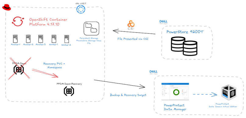
1000 Foot view of what we are doing:
If the diagrams are a little small, double click and it should open in a new tab. In short what we will demo is as follows:
We will present a File based storage target to our OCP Cluster via the Dell CSM/CSI Module.
We will spin up a new OCP namespace called ‘PPDM-Demo’. In this namespace we will deploy a demo application/pod ( Trust me this will be really simple) and configure this pod to consume our Powerstore File storage by using a Persistent Volume Claim or PVC.
At this point our cluster has no secondary storage configured, so if anything should happen to our new application then we will have no means of recovering it. Enter PPDM! We will overview the process to attach PPDM to our OCP cluster.
We will show how easy it is to configure a protection and recovery policy to enable Data Protection for our new application and namespace.
Disaster strikes!!! We will accidentally delete our application namespace from the OCP cluster.
Panic averted…. we will recovery our application workload to a net new namespace leveraging the backup copy stored on DDVE with an automated workflow initiated by PPDM.
We will break this post into two parts, this post will cover items 1 through 4 inclusive. In the next part of this post we will cover items 5 and 6.
Step 1: Create Test Namespace and Application Pod
As mentioned earlier, this won’t be anything too arduous. Log in to your OpenShift console as per normal, navigate to ‘Projects’, and click create ‘Project’.
I am going to give it the name ‘ppdm-demo’ and we are done!
Step 2: Verify Storage Class & VolumeSnapshotClass is configured.
Before we create our demo pod in the new ‘PPDM-Demo’ namespace, we will want to check if the Storage Class for Powerstore File and the VolumeSnapshotClass has been configured. This was preconfigured in my environment ( should be the job of your friendly storage admin perhaps)
Navigate to Storage -> StorageClasses. Here you can see we have two StorageClasses configured. The first for Block storage the second for File. Here you can see my Storage Class named powerstore-nfs provisioned by the dell PowerStore csi driver.
Step 3: Configure a PersistentVolumeClaim (PVC) and Verify.
Now that we have verified that our Storage Class and VolumeSnapshotClass are present, we will proceed to deploy some demo workload in our new namespace. As I said this is going to be very basic but it perfectly fine for demo purposes.
First up will will create a manual PersistentVolumeClaim. Navigate to Storage > PersistentVolumeClaims and then to ‘Create PersistentVolumeClaim’.
I have selected the nfs backed storage class, given my PersistentVolumeClaim a name ‘ppdm-claim-1’, and selected the RWX Access mode with a size of 5GB. Click ‘Create’.
Navigating to the YAML definition of the new PVC, I can see how it is configured, the access mode, the storage class name, its status which is immediately bound, volumeMode which is file. Note the new volume name ‘ocp11-7f9787520a’.
Navigate back to Persistent Volumes and you can see that a new Persistent Volume has been created with the Volume Name of ‘ocp11-7f9787520a’ associated with the PVC we just created ‘ppdm-claim-1’.
Next navigate to your PowerStore GUI and we can see that indeed we have created an NFS filesystem using CSI.
Step 4: Create your POD/Container/Application & attach to PVC
Now that we have our persistent storage setup, our PVC created and namespace configured, next up we will deploy our simple Linux based Pod. This time I will use the ‘Import YAML’ function in the OpenShift GUI. Navigate to the ‘+’ icon on the top right hand corner of the screen.
You can drag and drop directly into the editor, or just copy and paste directly.
Note the YAML file points to the claimName:ppdm-claim-1 and the namespace is ppdm-demo. Click ‘Create’.
Verify that your new POD is in a running state. You should also be able to attach to the Terminal. In the video demo I will create a test file so we can demonstrate persistence after we do the backup testing.
Configure Power Protect Data Manager
So now we have our application running in our OpenShift cluster backed by PowerStore persistent storage. Next we want to protect this application using Dell PowerProtect Data Manager and point the backups to our PowerProtect Data Domain device.
We won’t run through how to do the initial standup of PPDM and DDVE as I have covered this in other blogs. Link is here. We will start with a clean build, with DDVE already presented to PPDM as the backup storage repository.
Add Kubernetes as an Asset Source and Perform Discovery
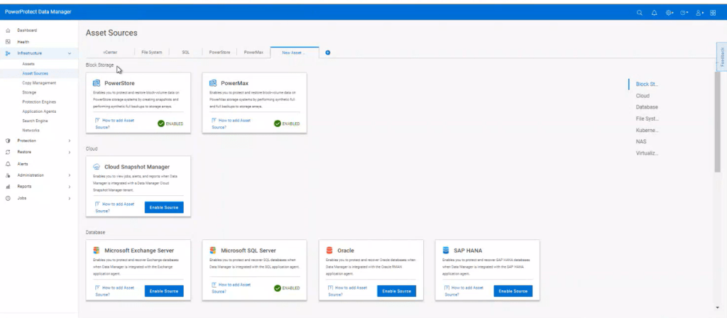
Log into PPDM, navigate to the left hand menu. Click Infrastructure -> Asset Sources. Scroll down until you find the Kubernetes Tile and then ‘Enable Source’.
You will be presented with an ‘Add’ Asset Sources under the new Kubernetes tab. Ignore that for now and we will come back to it, once we have our credentials configured.
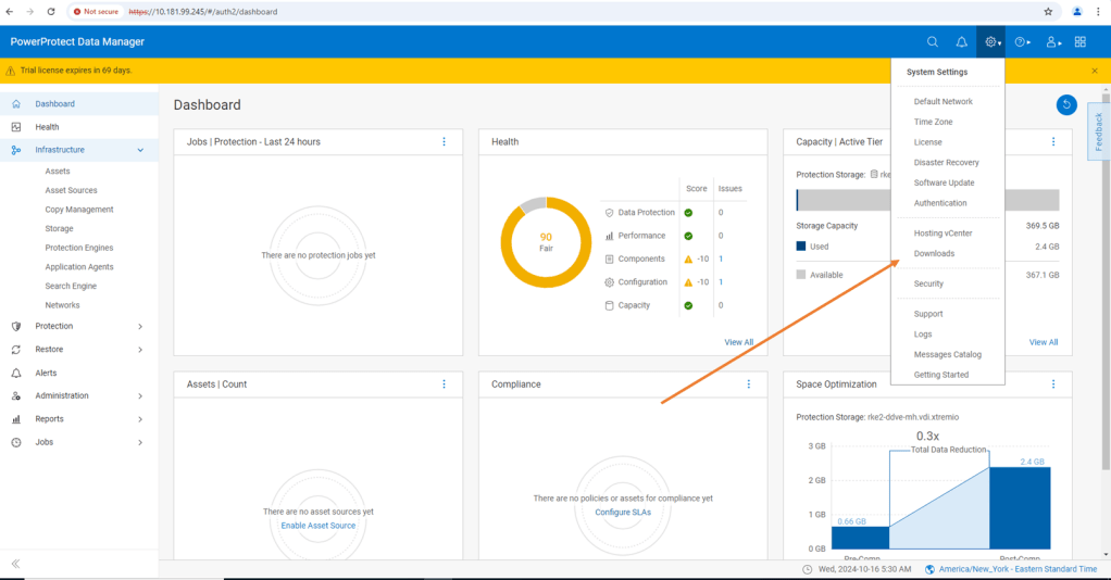
Now navigate to the downloads section of the GUI, under the gear icon in the top right hand corner.
Select Kubernetes and the RBAC tile. Click Download and save and extract to your local machine.
You will be presented with 3 files:
ppdm-controller-rbac.yaml
ppdm-discovery.yaml
README
We will use the two YAML files to setup the required service accounts, roles, role bindings and permissions, to allow PPDM discover, communicate and configure resources in the OpenShift environment. We will also create the secret for the ‘ppdm-discovery-serviceaccount’.
Navigate back to the OpenShift console and execute both YAML scripts, starting with the ‘ppdm-discovery.yaml’ file. Of course we could do this directly from the CLI also, but I like this feature of the GUI as it also allows you ‘drag and drop’ the raw files themselves.
Click ‘Create’ and this executes a ‘Kubectl apply’ command in the background.
All going well, you will be presented with a screen confirming that all resources were successfully created.
Follow the same process using the ppdm-controller-rbac.yaml file. You may get an error pointing to the fact that the ‘powerprotect’ namespace already exists. This is fine.
Next we need to generate the secret for the ‘ppdm-discovery-serviceaccount’. Using the console again execute the following YAML ( hint: if you read the README file it is in there !)
Import the YAML file into the console as per the previous step and click ‘Create’
OpenShift now generates the ‘ppdm-discovery-serviceaccount-token’ details. Scroll down to the bottom of the screen to the ‘TOKEN’ section and click the copy icon.
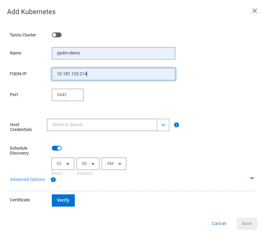
Now that we have the secret retrieved we can navigate back to our PPDM console and add the OpenShift Kubernetes cluster. Navigate to Infrastructure -> Asset Sources -> Add.
Follow the input form, pointing to the api of the openshift cluster. redact the https from the start. Leave the port as standard 6443. In the Host credentials field, select Add Credentials.
Give the credential set a name and paste the token you copied earlier into the Service Account Token field and click Save.
Verify and accept the cert and then click Save.
After a few seconds, the newly discovered Asset Source should appear and an automatic workload discovery will be initiated by PPDM.
Navigate to the Assts tab and after the automated discovery you can see the discovered namespaces in the cluster. Including the ‘ppdm-test’ namespace we created earlier!
Configure Protection Policy
The next logical step of course is to configure a Protection Policy for our OpenShift Project ‘ppdm-demo’ and protect all the underlying Kubernetes resources, PVC’s etc. under its control.
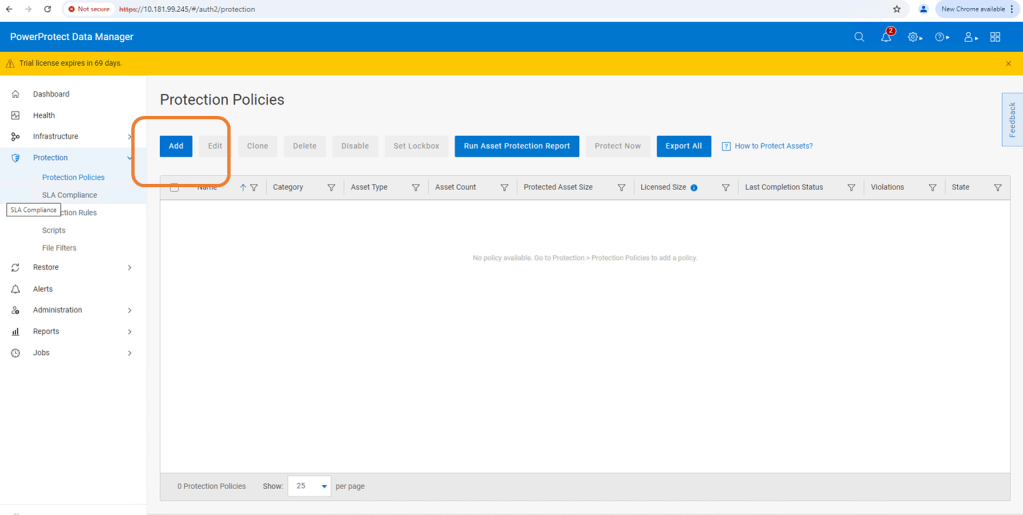
First step navigate to Protection -> Protection Policies and click ‘Add’. Follow the GUI guided path.
Select ‘Crash Consistent’ which snapshots the PVC bound to our application and backs it up on our target backup storage on Data Domain.
Add the asset namespace that we wish to protect.
Then step through the GUI to configure the primary back target, which of course is our backend DDVE. I have selected a Full backup, every 8 hours and we will retain for 1 day.
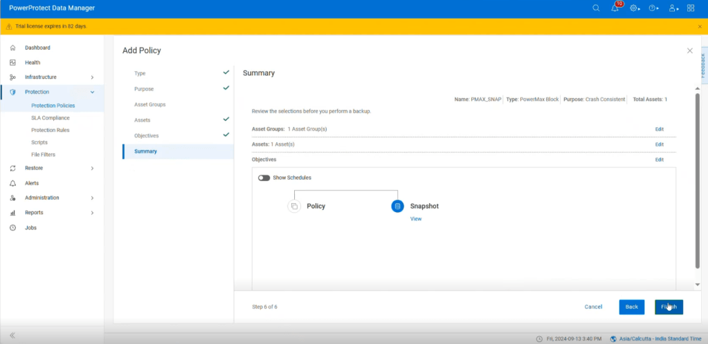
Follow through to the summary menu and click Finish.
Manually run the Protection Policy
We could wait until the policy kicks off the backup at the designated time, but we will want to verify it works and plus I am a little impatient. Thus, we are going to take the option to ‘Protect Now’. Navigate back to Protection -> Protection Policies and select our new policy. Click on ‘Protect Now’.
Step through the GUI, selecting the Full backup option and kick off the job. Navigate to the Jobs menu on the sidebar and monitor the Job as it completes. Dependent on the size of the namespace to be backed up this will of course take some time.
Eventually the Job completes successfully.
Up Next
Next week, I will follow up with our orchestrated disaster, whereby I will accidently delete my running application, namespace, POD and associated PVC.
I think this is probably deserving of a Video demo also which will capture the whole process end to end!
DISCLAIMER
The views expressed on this site are strictly my own and do not necessarily reflect the opinions or views of Dell Technologies. Please always check official documentation to verify technical information.
Power Protect Data Manager 19.18 dropped earlier today. A fair bit to unpack but 3 main highlights for me. I hope to delve into more detail around these (especially around the exciting new anomaly detection feature) in future posts. In the meantime a quick overview:
1. NetApp as an explicit array type/NAS Asset Source
NetApp is added as an explicit array type that can be selected when adding a NAS asset source. This selection allows NetApp appliances to more easily integrate into NAS protection workflows.
This is pretty much hot off the press, but here is the link to the official NAS configuration guide where you can find more detail. You will need to register to view.
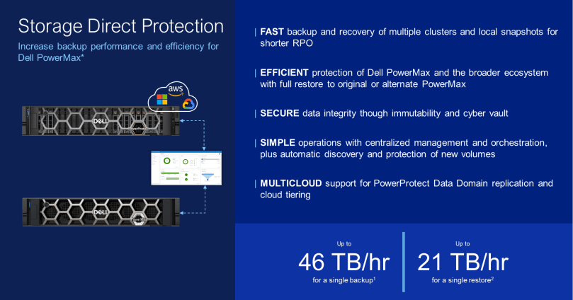
Integrated PowerStore Snapshot Management allowing for the simple policy management for the creation and retention and deletion of array based snapshots has been available since PPDM release 19.14. Release 19.18, brings feature parity to the PowerMax array, and builds on the much tighter integration with PowerMax with Storage Direct introduced in Release 19.17. I blogged about this feature back in late July. Click here to view the blog on Storage Direct Protection.
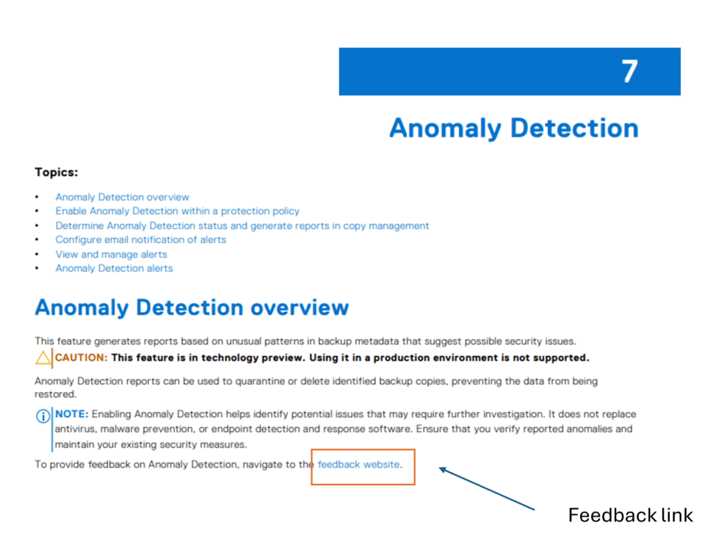
Last but not least, This is the new feature that was introduced as a Beta in 19.17, but now in Tech Preview in 19.18. ( Tech Preview basically means that it is officially released but not yet ready for full production use just yet). I have included a link below, where customers can send feature feedback .
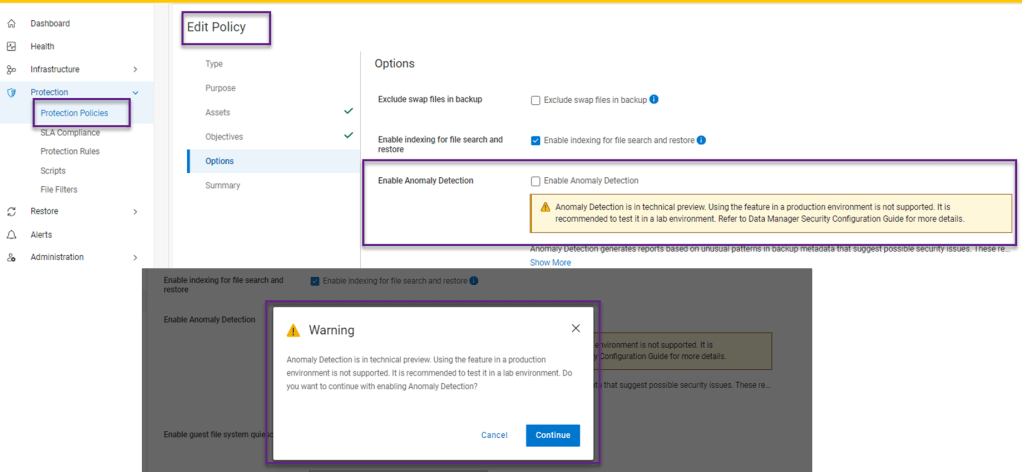
Anomaly Detection generates reports based on unusual patterns in backup metadata that suggest possible security issues. Whilst enabling Anomaly Detection helps identify potential issues that may require further investigation, it does not replace antivirus, malware prevention, or endpoint detection and response software. Ensure that you verify reported anomalies and maintain your existing security measures. ( Really just stating the obvious here… defense in depth and all that !)
Its worth noting that this feature adds an extra layer of security to data without adding any additional licensing or cost. Yep it’s included in the existing license.
I’ve grabbed some screenshots from the latest release to give a ‘look and feel’ of this new functionality. As mentioned I will follow up with a more technically focused blog and demo.
Enabling Anomaly Detectionwithin the Protection Policy Tab
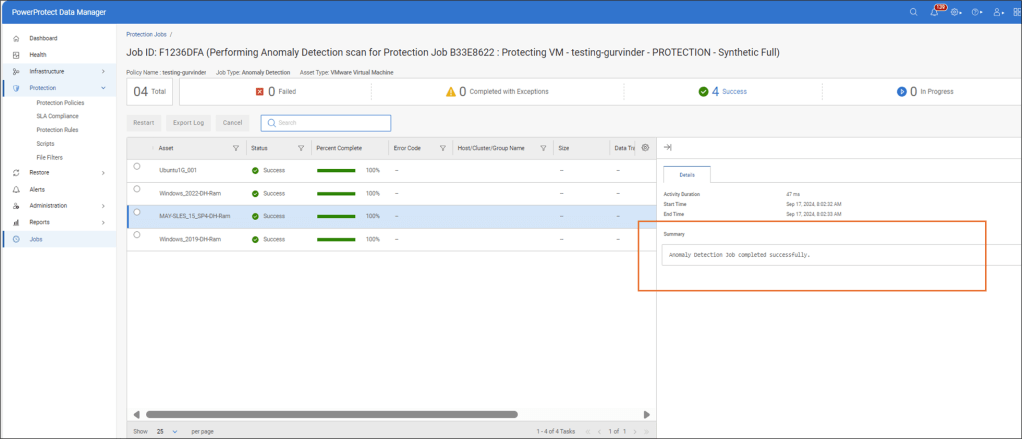
Completed Job with no Anomaly Detected
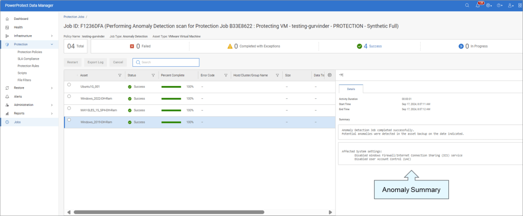
Completed Job with Anomaly Detected
Jobs View with Anomaly Detected
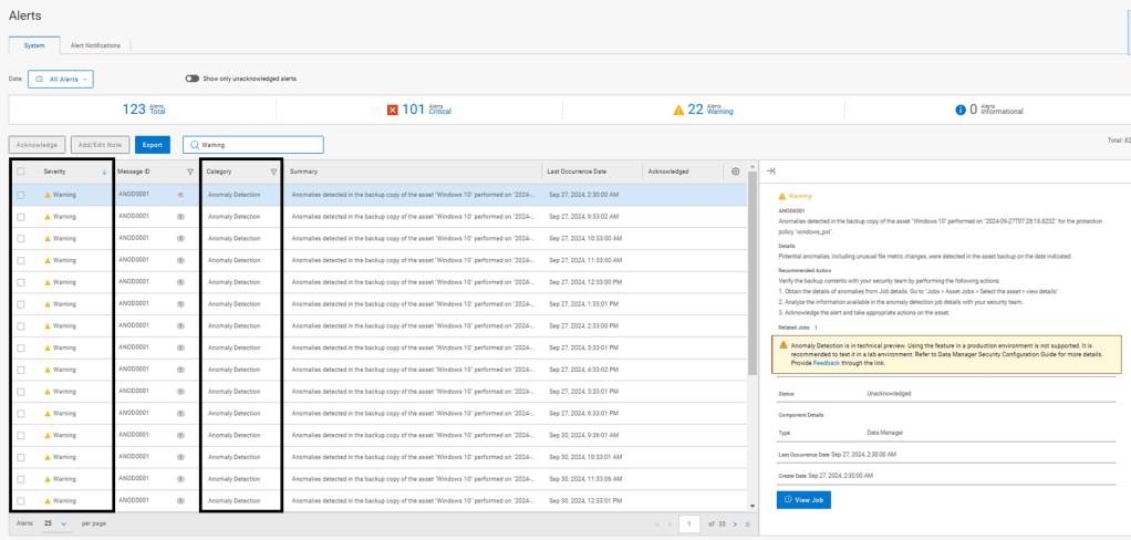
Critical Alerts View
Anomaly Detection – Warning Alerts
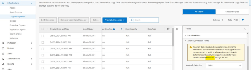
Copy Management View
Reporting View
Reports are available for download in case of suspicious copies.
Quarantine or Mark Copy Safe
Link to Provide Feature Feedback
As mentioned above, this feature is in Tech Preview. Please provide feedback via the following
Detail on feedback is also provided here in the Security Configuration guide.
Lots of detail is included in Chapter 7 Anomaly Detection
I admit the link is buried in the documentation. It can be located at the following: Note: I say this documentation set as it potentially is subject to change:
Stay tuned for deeper dive into the exciting new Anomaly Detection feature in an upcoming post.
DISCLAIMER
The views expressed on this site are strictly my own and do not necessarily reflect the opinions or views of Dell Technologies. Please always check official documentation to verify technical information.
Rancher Managed RKE2 Cluster deployed. Link to blog post here.
Dell CSI for PowerScale configured to present persistent storage to our environment.
An application running in our environment in a new production namespace writing data to a PowerScale NFS target. Link to CSI configuration and demo application blog post here.
Protection Environment:
Dell PowerProtect Data Manager deployed and running. Link to post here.
Backed by Dell PowerProtect Data Domain (APEX Protection Storage)
The next step is to demonstrate how we knit our ‘Production Environment’ and our ‘Protection Environment’ together.
Use of External Load Balancer:
If this was a production environment, where we have distributed the K8s control plane across all 3 active nodes, then we would deploy an external TCP/HTTP Load Balancer such as HAProxy in front of the control plane to distribute API activity into the cluster and provide HA for the API access process. Clearly this is a really important topic and we will dig into it in more detail in an upcoming blog post ( when we do this in production we don’t want stuff to break!). For now though, to keep things simple lets park that conversation and point PPDM directly at one of the active control plane nodes in the cluster.
Step 1: Discovering RKE2 Kubernetes Cluster
Natively within our Kubernetes cluster within the kube-system namespace, the necessary user permissions exist to execute the discovery and to allow PPDM to configure the RKE2 cluster via the API. (We will see later that PPDM configures a new namespace and deploys the Velero application etc). Personally, I have a preference to segregate this activity to a new user bound with net new permissions. Luckily this is a straightforward process and you can download and deploy the necessary YAML configuration files direct from PPDM and execute on your cluster. This is the approach we will take here.
1.1 Download YAML Files to your Management machine
Log into PPDM and navigate to ‘Downloads’ under the gear icon at the top right of the GUI
From there, open the Kubernetes tab on the left hand side and download the RBAC file. Extract the folder to a local directory. The folder contains 2 YAML files and a README file.
ppdm-controller-rbac.yaml
ppdm-discovery.yaml
The first file sets up the PPDM controller service account and RBAC permissions, the second the PPDM discovery service account and associated permissions.
1.2 Configure RKE2 Cluster with both YAML files.
There are a couple of ways to execute this, Rancher makes this really easy for the those not to familiar with the Kubectl command line. ( Although in reality this is just copy and paste in any regard)
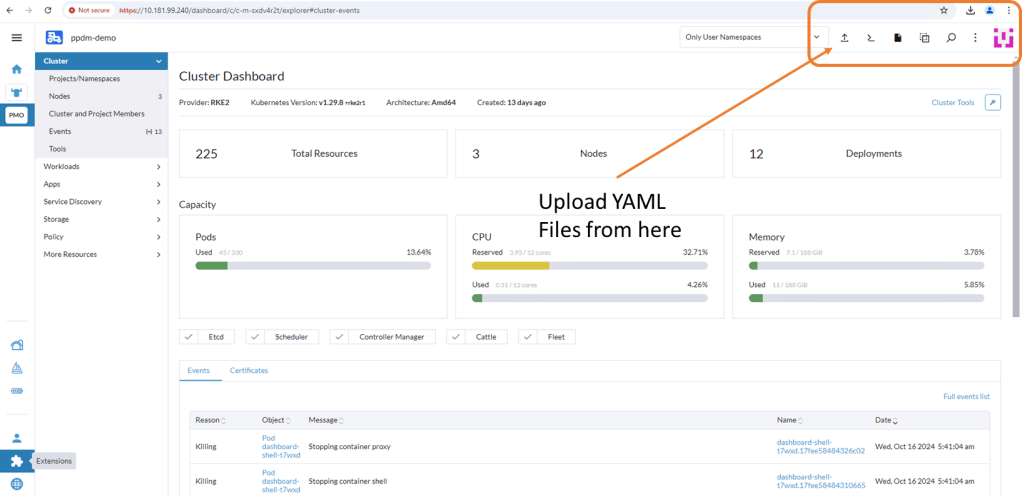
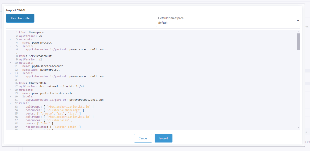
Log back into Rancher and navigate back to our demo cluster and to the ‘Cluster Dashboard’ view. There is a touch of ‘blink and you miss it’ but at the top right hand corner there is an ‘upload’ icon.
Click ‘Read from File’ and then ‘Import’ the first YAML file (ppdm-controller-rbac) into the default namespace.
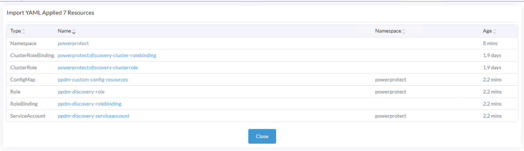
You should get a verification that the cluster was configured with a new Namespace ‘powerprotect’, a new ClusterRole, Service account etc.
Repeat the process for the second YAML you downloaded (ppdm-discovery.yaml)
As you can see this creates another ServiceAccount amongst other entities within the new powerprotect namespace.
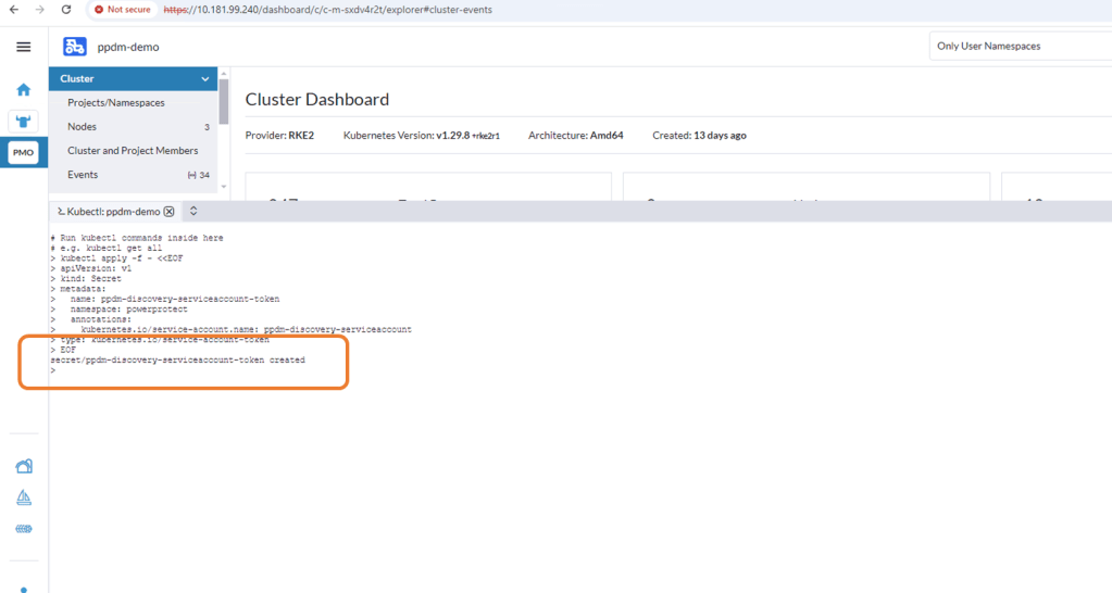
1.3 Create the secret for the PPDM-Discovery-ServiceAccount
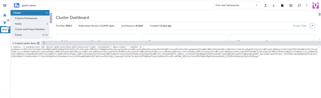
For K8s deployments after 1.24, we need to manually create the secret associated with the service account. Open the Kubectl Shell in Rancher.
I have seen on occasion, a situation whereby an additional ‘>’ gets appended as the trailing character of the above output. This will cause the asset discovery process to fail as the secrets won’t match between PPDM and the RKE2 cluster. I have used the following command also and this does not attach the trailing ‘>’
Log into PPDM , navigate to the ‘Infrastructure’ tab, then ‘Asset Sources’. Scroll down through the GUI until you see the ‘Kubernetes' tile. Click ‘Enable Source’.
2.2 Configure the Kubernetes Asset Source
Under ‘Asset Sources’, Click ‘Add’. This will guide us through the wizard.
In the next pane, give the Kubernetes cluster a meaningful name, I have chosen the cluster name itself. Note As outlined above I have pointed it to the API interface of the first control plane node. In a production environment this will be the Load Balancer IP address. Also, a much as I harp on about DNS everywhere, I am pointing to a physical IP address and not the FQDN. Leave the discovery port as the default 6443.
Under the ‘Host Credentials’ field, click the dropdown and ‘Add Credentials’. This is where we will inject the ‘secret’ we extracted form the RKE2 cluster (remember be careful of trailing ‘>’). Give the credential a name ( can be anything) and paste in the Service Account Token. Then click ‘Save’.
Proceed to ‘Verify’ and ‘Accept’ the certificate and then Save. The asset source should appear in the ‘Asset Sources’ window. Navigating to the System Jobs panel, you will see PPDM undergoing an asset discovery.
Navigate back to the Assets tab and we can see the discovery has completed and we can see all our namespaces in the RKE2 cluster ( including our system namespaces).
Step 3: Configure Protection Policy for Production Namespace.
Now that we have the end to end infrastructure built, deployed and discovered, we now need to create a policy in PPDM to protect our production application, which resides in the ‘dell-ppdm-demo’ namespace. Lots of screengrabs upcoming, but don’t worry too much if you miss something… it will be in the attached video also.
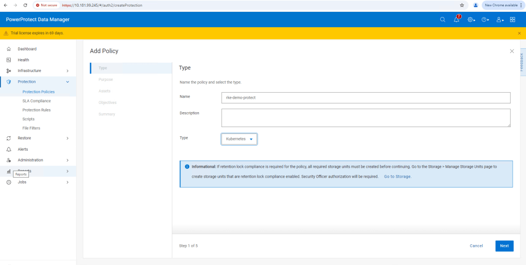
3.1 Create Protection Policy
This really is a very straightforward process. Navigate to the Protection tab and then ‘Protection Policies’. Click ‘Add’.
Follow the Wizard guided path.
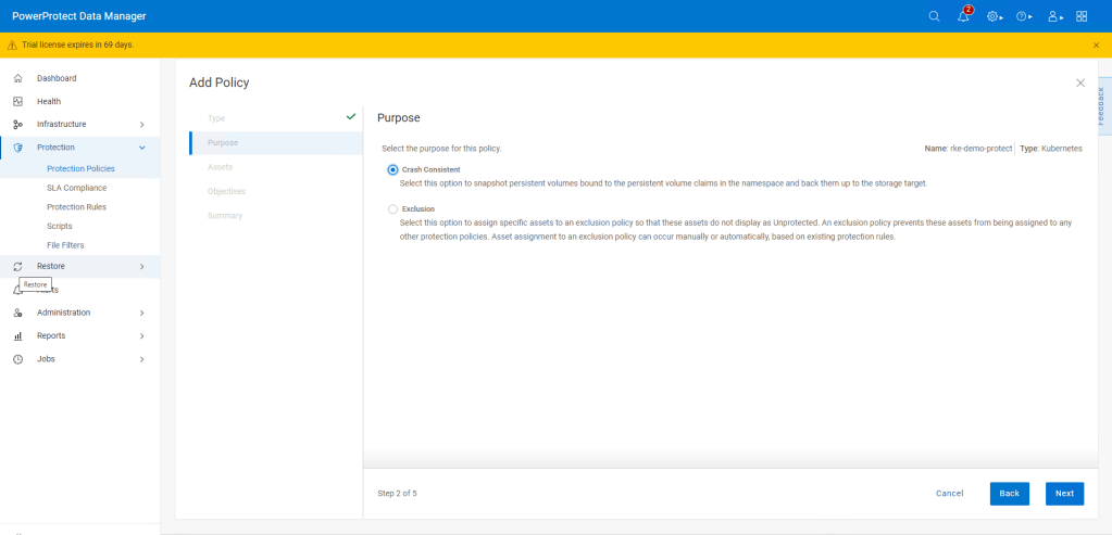
For this demo I am using ‘Crash Consistent’.
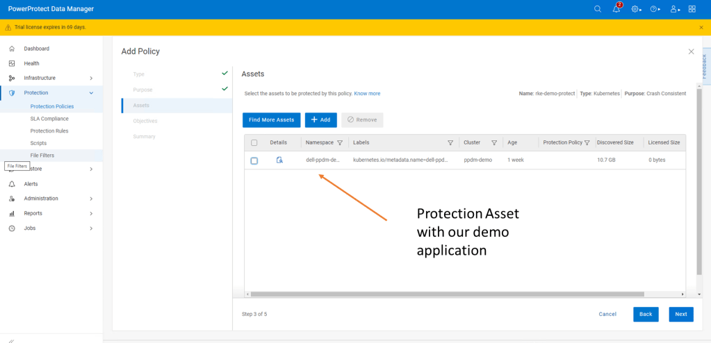
Click next and then add the namespace that contains the application that we have configured. In this case ‘dell-ppdm-demo’.
Next configure our Protection policy objectives, when and where we want to push the backup. Do we want to replicate a secondary copy to the cloud for instance or to a preconfigured cloud tier? For this demo we will keep it simple. We are going to push a ‘Full’ backup to the DDVE instance we have paired with PPDM in the last blog.
Click ‘Add’ under primary backup, and configure the policy parameters. I am going to push a full backup every 1 hour and retain for 1 day, starting at 9 AM and Ending at 9 PM.
Click ‘Next’ and then ‘Finish’.
There you go, this is really incredibly simple. At the next screen, we could wait until the protection policy kicks off as per the schedule but we will cheat a little and run the protection manually ( after the next step!).
Step 4: Configure your Cluster for Snapshot capability
So whilst we have the CSI driver installed on our cluster, we have skipped over one really important step. If we attempt to do a restore or replicate the application to a new namespace ( as we will show in the video), it will fail. The reason being we being we have installed no snapshot capability on the cluster yet.
I have covered this in detail, when we discussed PPDM in an EKS environment. Link to this is here. For now though, follow the following steps.
4.1 Install external CSI Snapshotter
Run the following commands on your cluster using Kubectl.
Verify it is deployed using the ‘Kubectl get VolumeSnapShotClass‘ command.
Step 5: Test the Protection Policy
Now that we have everything configured properly, we will want to test that the protection policy is functioning. For a scheduled policy we could wait until the scheduled time but for the purposes of the demo we will initiate this manually.
5.1 Invoke ‘Protect Now’
Under Protection Policies, select the protection policy we created earlier. And Click on the ‘Protect Now’ button.
Navigate through the rest of the guided path. On this occasion we will select ‘Full Backup’ versus ‘Synthetic Full’. As it is the first time we have done the backup, technically there will be no difference in any regard.
The Protection Job will kick off and be queued for execution. You can follow its progress via the Jobs tab. All going well, as below, the job should complete successfully.
Step 6: Deploy new namespace from backup.
This will be demonstrated more readily in the video. We will execute a really simple test by:
Deleting the Namespace ‘Dell-PPDM-DEMO’ and everything in it, including our application. This might simulate a user error for instance.
Recover the namespace and the application via PPDM
Log back into our recovered application.
Let’s delete our namespace by using the ‘Kubectl delete ns dell-ppdm-demo‘ command:
Step 6.1 Recover Namespace and application from PPDM
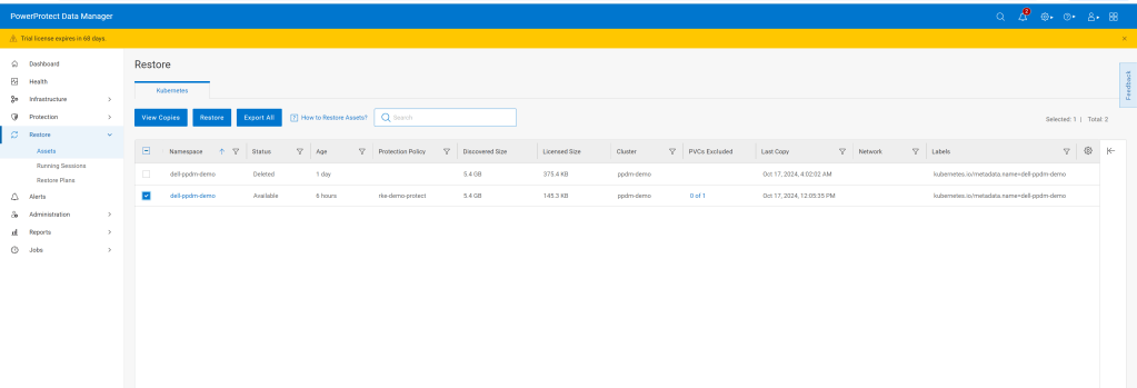
Luckily we have a backup of the namespace. Navigate to the Restore tab in PPDM and select our policy and click ‘Restore’
Navigate through the rest of the GUI, its very straightforward. We are going to restore to the original cluster, restore the namespace and associated PVC’s, including all scoped resources. For demo purposes we will restore to newly named namespace called ‘restored-ppdm-demo’.
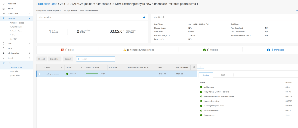
Navigate to the Protection Jobs menu and monitor progress
All going well, dependent on the size of the restore, the operation is a success:
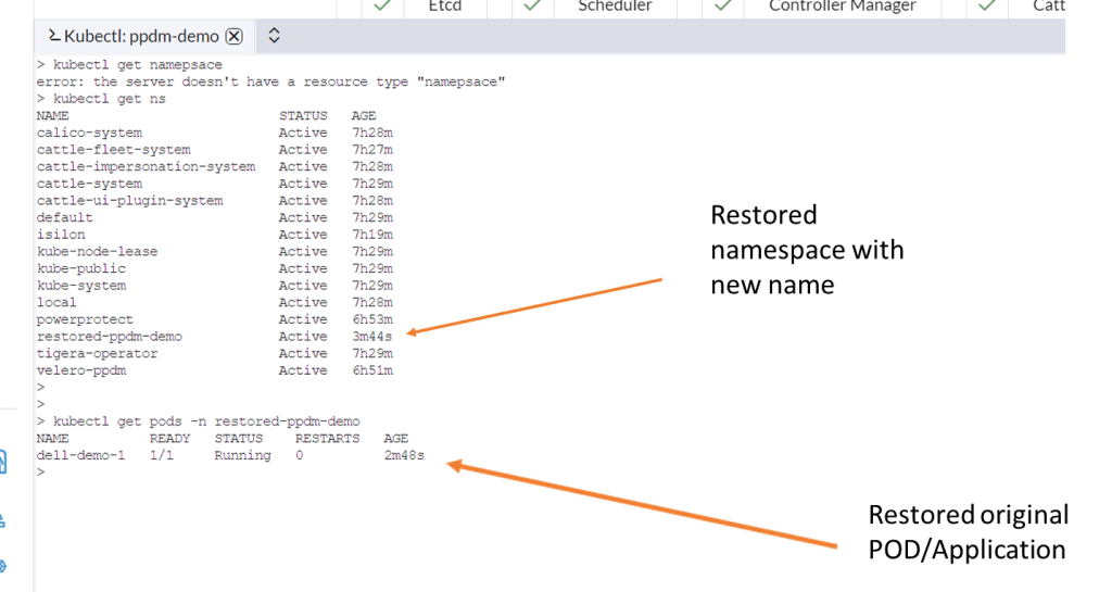
Navigate back to Rancher and lets have a look back in to the cluster to see can we see the restored namespace and associated POD.
Video Demo
DISCLAIMER
The views expressed on this site are strictly my own and do not necessarily reflect the opinions or views of Dell Technologies. Please always check official documentation to verify technical information.
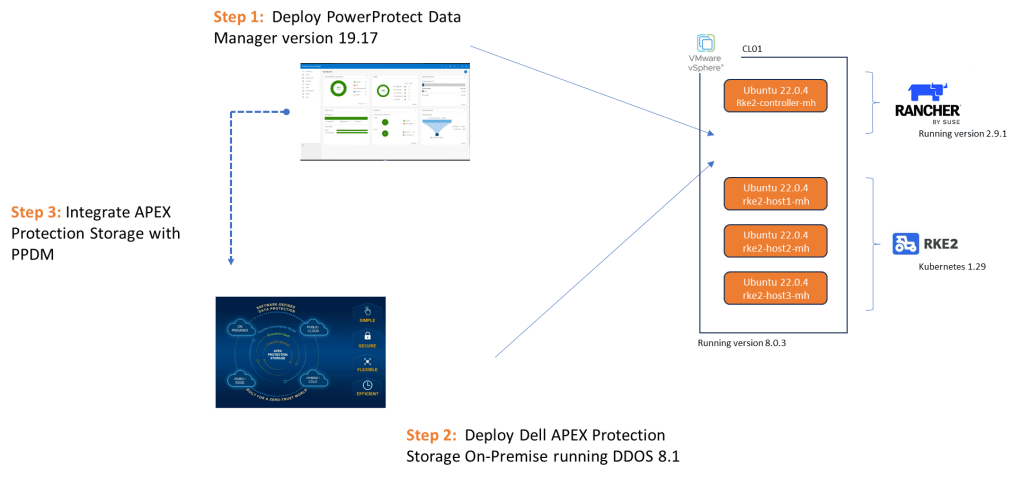
In Part 1, we stood up the Rancher Manager and deployed our 3 Node bare-Metal RKE2 cluster. In Part 2, we deployed Dell PowerProtect Data Manager 19.17 and paired it with a fresh installation of Dell APEX Protection Storage On-Premise running DDoS version 8.1 (Previously known as Data Domain Virtual Edition – or DDVE for short).
I probably could have reversed the order here and done the following after part 1, but I wanted to get straight into some context around PPDM ( This is after all what this series is ultimately about!).
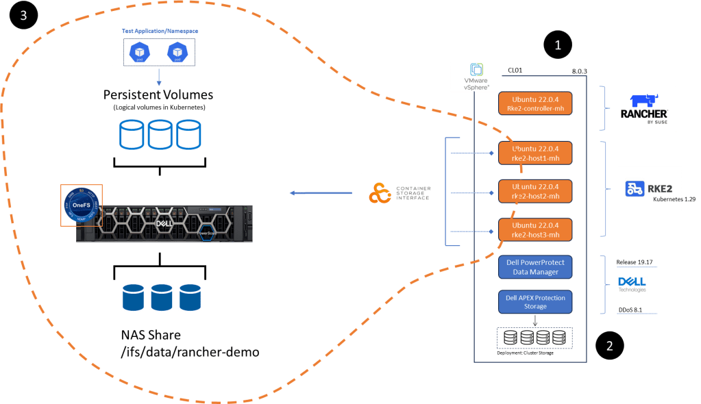
Bottom line we need to deploy some applications to protect. To that end Part 3 will focus on everything inside the orange dashed line, namely:
Configuration of NAS, NFS share on Dell PowerScale appliance running OneFS 9.8. I am running a virtualised version in my lab but this of course could be a physical appliance. This is already up an running so I won’t run though the setup in this series.
Dell CSI (Container Storage Interface) for PowerScale installation and configuration on our pre-existing RKE2 cluster ( the one we configured in Part 1 of the series). We will point the cluster to write to Persistent volumes created on the PowerScale NFS share.
Setup of demo application RKE2 POD in the environment to test everything is working as it should be….. be nice as I am no developer! This will be short, simple and to the point!
Step 1: Configure PowerScale NAS Share and Present to RKE2 Cluster
This really is incredibly straightforward. You do not have to be an expert to navigate yourself around the OneFS interface.
Configure NFS Share on OneFS
Under the protocols tab navigate to Global Settings and confirm that NFS v4 is has been enabled.
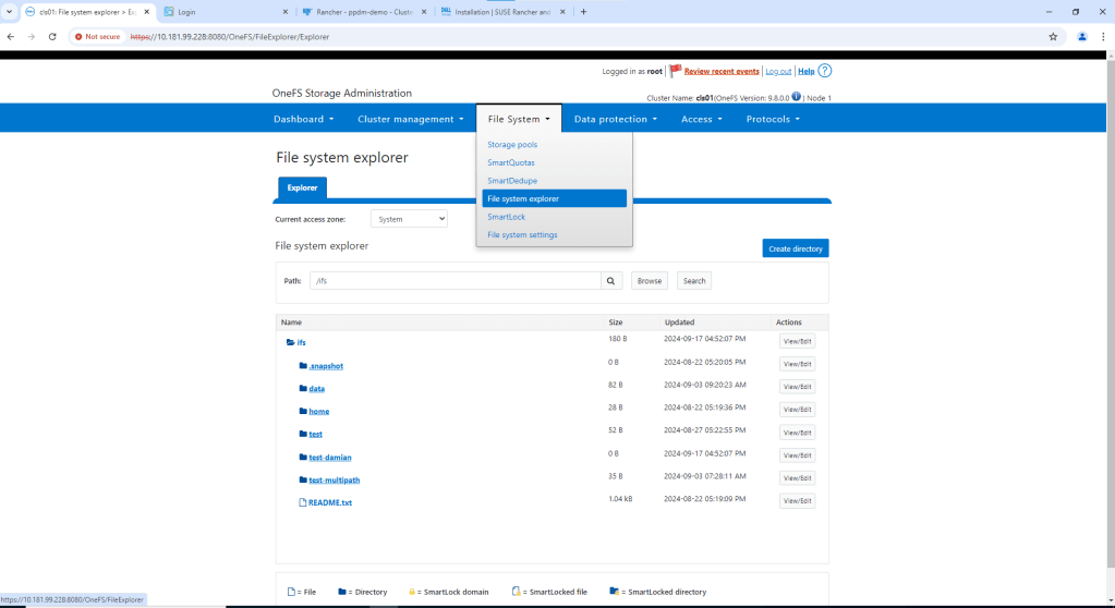
Navigate to File System -> File System Explorer. Then click ‘Create Directory’
Check that your path and permissions are set appropriately. Note, this is a test environment, so I will enable everything. Click ‘Create directory’ again.
Navigate to the newly created directory using the File System explorer. Check the path is as expected. There should be no data in the directory.
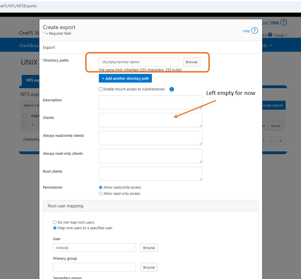
Navigate back to the ‘Protocols’ tab and to UNIX sharing (NFS). Click ‘Create Export’.
Create the export by adding the Directory Path /ifs/data/rancher-demo. Again this is a test environment, so I have left all my default settings as is. I also didn’t populate the clients tab, which will add another layer of access authorisation. By leaving blank we give everybody access. Scroll down and ‘Create export’.
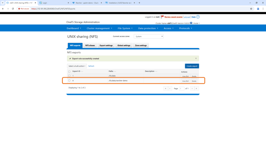
Verify NFS Export exists and the configured path is correct
Step 2: Install Dell CSI on RKE2 Cluster
In a future post we will do all of the following via code (blog around PowerFlex integration). For now though we will use the Rancher interface. This really simplifies the process. I will attach links to the GitHub etc. at the bottom of this post , where everything is really well documented.
Prerequisites
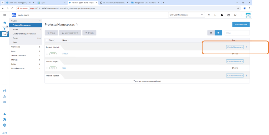
1. Create namespace named isilon
Navigate to the RKE2 Cluster we created in Rancher. Navigate to the Projects/Namespaces tab and ‘Create Namespace’.
Leave the defaults but make sure that the namespace is named correctly as ‘isilon’.
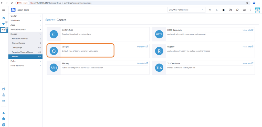
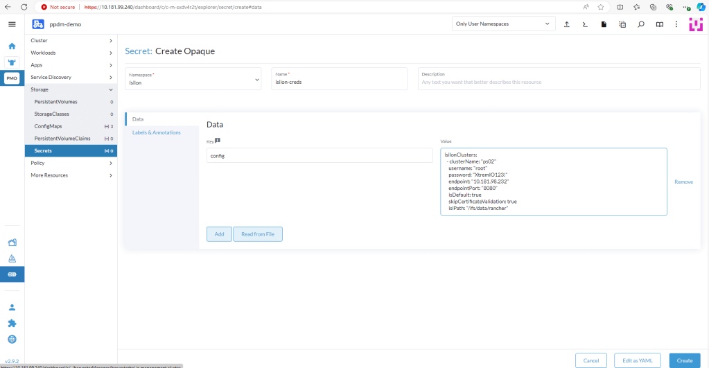
2. Create an opaque secret named “isilon-creds” in the newly created isilon namespace.
You really need to be careful of the syntax here. I will add a link at the bottom to the github for the detailed documentation and the source yaml file, but the following should work:
where the ‘Clustername’ is my Powerscale cluster name. The isiPath is my NFS share. Change the Data key to ‘config’ and click ‘Create’.
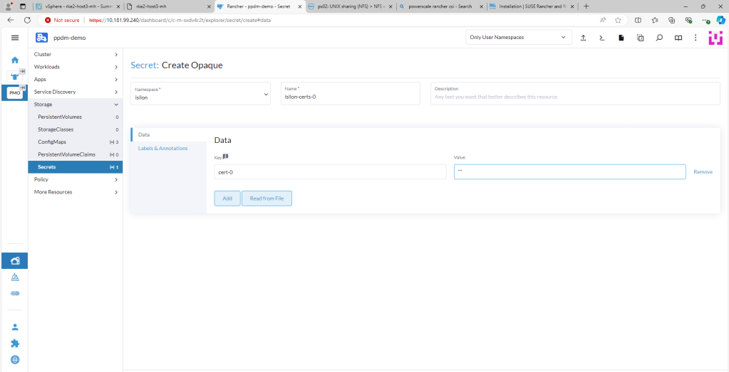
3. Create an Opaque Secret named isilon-certs-0 in the isilon namespace.
Again, syntax and case sensitivity are key or this will fail. Populate the value field with “”. The Data field key is ‘cert-0’ – case sensitive!
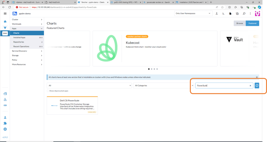
4. Install Powerscale CSI using HELM Chart
Navigate to Apps, then Charts and search for Powerscale. Click on Dell CSI for PowerScale.
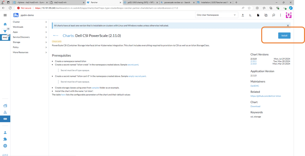
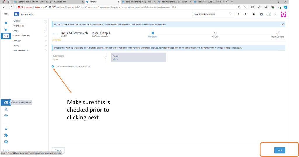
On the next screen, double check the prerequisites (which we have already done) and then click ‘Install’
Check the ‘Customize-Helm Options before Install and then ‘Next’. We need to change the ISI Path in the YAML Manifest.
Edit the ISI Path to match the export you have created in PowerScale. Click Next and then ‘Install’.
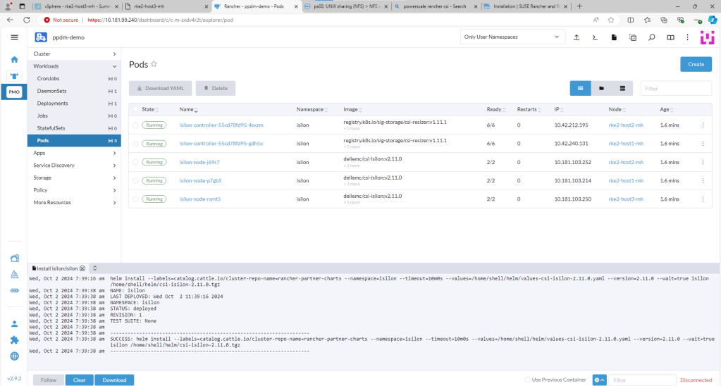
Confirm the installation has been successful.
You can check this via Kubectl also by opening the Shell and running the ‘Kubectl get pods -n isilon’ command. All Pods should be in a Running state.
Step 3 : Deploy Demo App in New Namespace
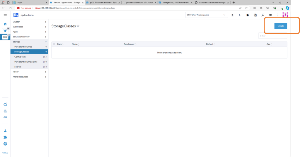
1. Create Storage Class
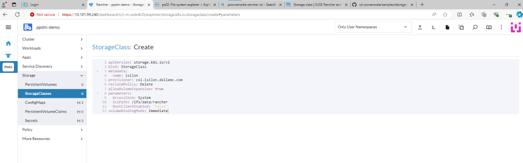
You can find the link to the sample storage class I configured here. For a bit of clarity I have redacted all the comments in the code. This is just a sample, you can change other parameters here such as the VolumeBindingMode etc. Just make sure the IsiPath matches the path configured in Powerscale.
Navigate to the StorageClasses tab and click ‘Create’. We will run through this step on the video in part 4 also.
Now we could do this via Kubectl, or through the menu or in my case I’m just going to copy and paste my YAML file above.
Delete the pre-populated YAML code and paste your snippet. Making sure we point to the correct ‘Isi’ path. Click ‘Create’. Job done!!
2. Create PersistentVolumeClaim
The following example is really simple, for more examples you can point back to the Dell Github. For the purposes of this demo, it is enough to understand that we need some mechanism for our user ( in this case pod) to request storage from the underlying storage provider i.e Powerscale. We do this via the PVC construct.
Again the process in Rancher is extremely straightforward. Navigate to the PersistentVolumeClaim tab, and from there click ‘Create’. On the next screen, click on the ‘Edit as YAML’ button.
Delete, the pre-populated code and paste our snippet above. Notice you will get an error as we have not yet created our new namespace “dell-ppdm-demo”. You can very quickly do this with kubectl directly from the console.
couldn’t be easier. One command!
Next back to our upload YAML again, this time no errors. This time it creates successfully and is automatically transitioned to ‘bound’ state.
3. Create application backed by Powerscale Persistent Storage.
This is as super simple Pod that I will create manually in the newly created namespace, backed by Powerscale persistent storage. It is enough to demo backup and recovery in part 4, the next and final part of this series.
I will deploy a little application that writes the time and date to a file every 5 seconds. enough to a) populate some data into the filesystem and b) give us a de-facto timestamp so that we can verify the recover sequence.
Navigate to Pods and then ‘Create’. Click ‘Edit as YAML’.
Delete the pre-existing YAML code and paste in the following. This will deploy a single POD into our new namespace, backed by Powerscale storage. Click ‘Create’.
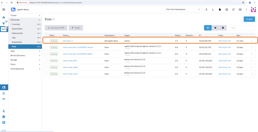
After a few seconds the Pod will deploy and you should see the following. Note, it is deployed in the ‘dell-ppdm-demo’ namespace.
Let’s have a look via Kubectl to see the state of our PVC and the POD itself.
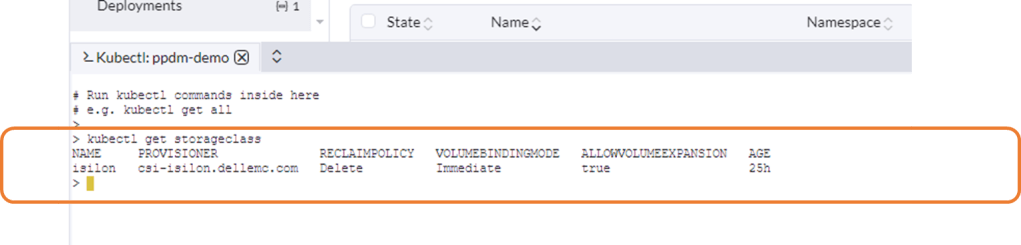
StorageClass looks good!
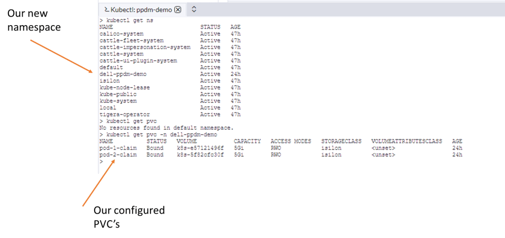
Our newly configured namespace and PVC’s…
Our Pod is up and running plus we are writing data.
We can browse to the OneFS interface to see the folder created (note the same name as the PVC) and that data is being injected into the file ‘out.txt’.
Up Next
In the next and final part of this series, we will discover our RKE2 Kubernetes cluster via PPDM and create a protection policy to backup the relevant namespaces, persistent volume claims etc. Of course at that point we will demo a failure and recovery and see everything in action.
DISCLAIMER
The views expressed on this site are strictly my own and do not necessarily reflect the opinions or views of Dell Technologies. Please always check official documentation to verify technical information.
In Part 1, we stood up the Rancher managed RKE2 in our vSphere environment (mirroring a bare metal deployment). The next step is to set up the protection infrastructure, namely Dell PowerProtect Data Manager and On-Prem Dell APEX Protection Storage (Formerly branded as DDVE)
Note: whilst this is the second part of this blog series, you can use this post as a stand alone reference to quickly deploy an on-premise PPDM and APEX protection Storage environment.
As ever pre-requisites apply…. DNS, DNS, NTP and more NTP. I have also included a video demo of the entire process and links to key collateral ( note: you may need partner/employee credentials to access some of the downloads and content)
Step 1: Deploy PowerProtect Data Manager Version 19.17
I’ll step through this on in the video. I’m going to assume that this should be straightforward enough. I’m going to deploy on the same cluster where my RKE2 cluster resides.
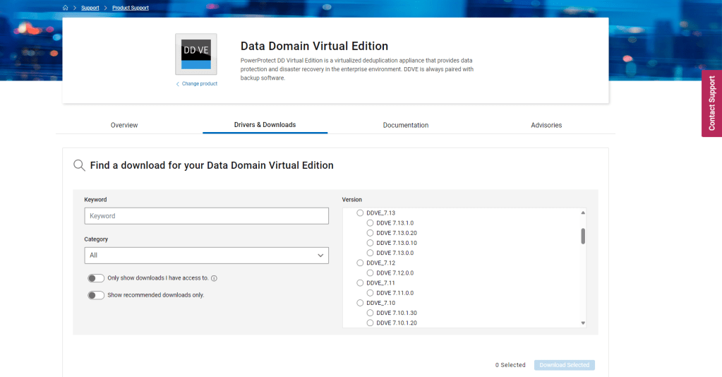
I have saved the file to my local drive, where you can upload from directly.
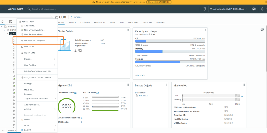
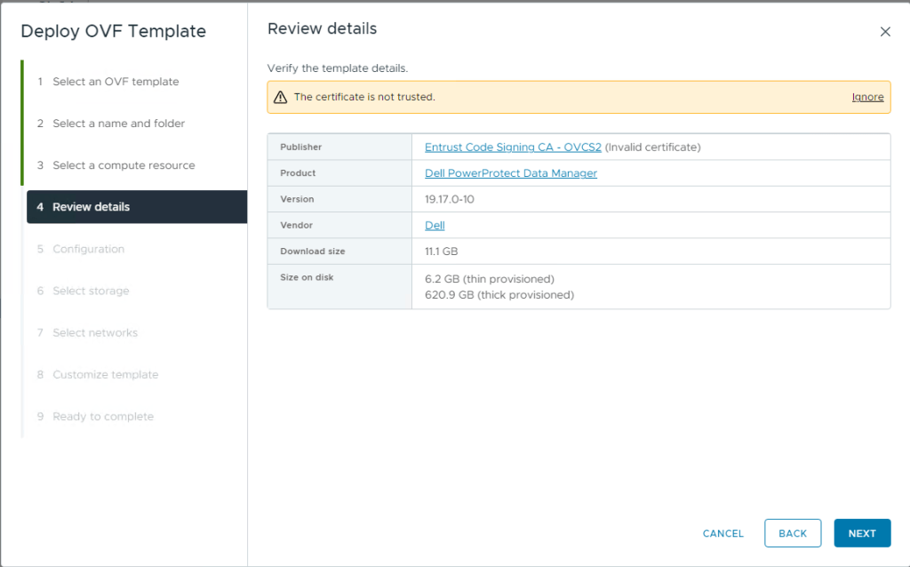
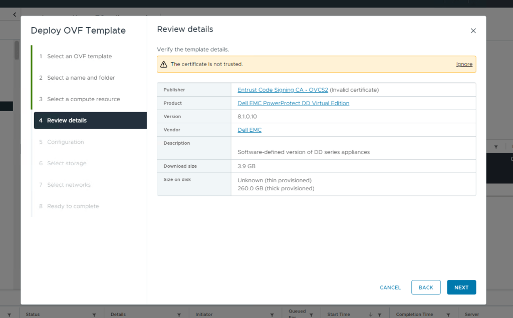
Run through the template workflow, give the Virtual Machine a name, ignore the certificate error and use thick provisioning as recommended.
This is a VMware (on-premise/hybrid) deployment.
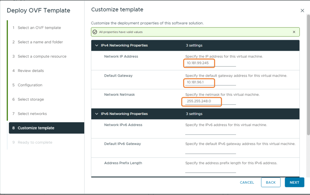
For this deployment I am connecting to the same network as my RKE2 hosts, but this could be any network as long as their is IP reachability to the K8s cluster and APEX Protection Storage device.
For the next section, this is where we need to ensure we have forward/reverse DNS setup in our environment.
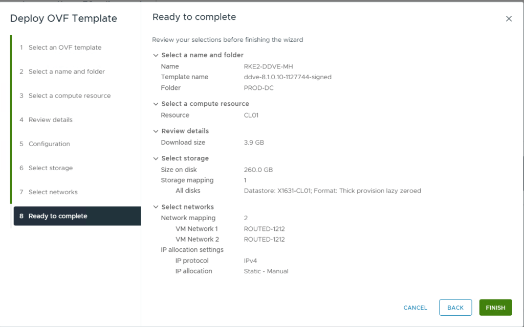
Finally, check all your settings are ok. Mine are good here, datastore is correct, format is Thick provisioned Lazy zeroed, I am connected to the correct network and most importantly my DNS and IP settings are valid. Click Finish.
This will take sometime to deploy, you can monitor the progress on the vCenter taskbar.
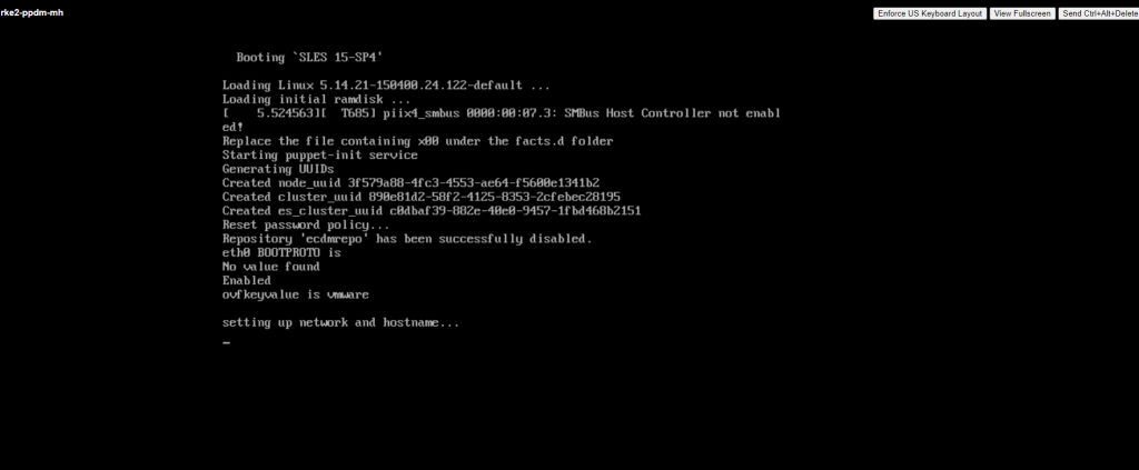
Once deployed, right click the VM and Power-On. Go grab some tea, the machine will take a couple of minutes to boot and all the services to start properly.
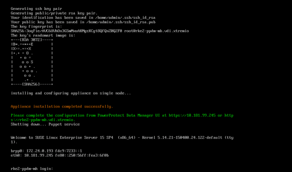
You can monitor progress by opening the VM console
After a few minutes, the application is installed successfully
3. Initial Configuration of PowerProtect Data Manager
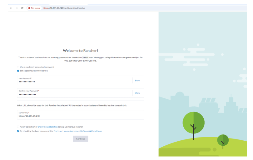
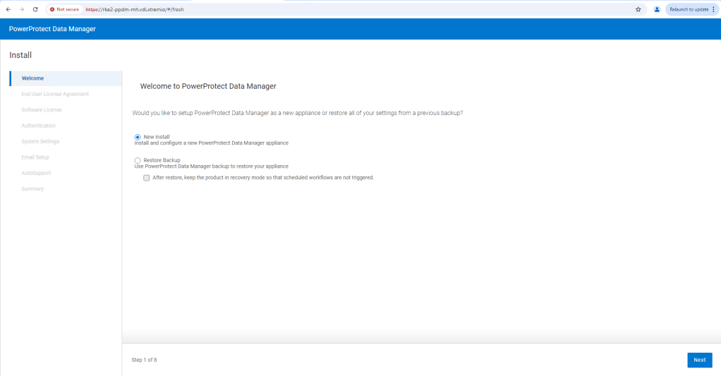
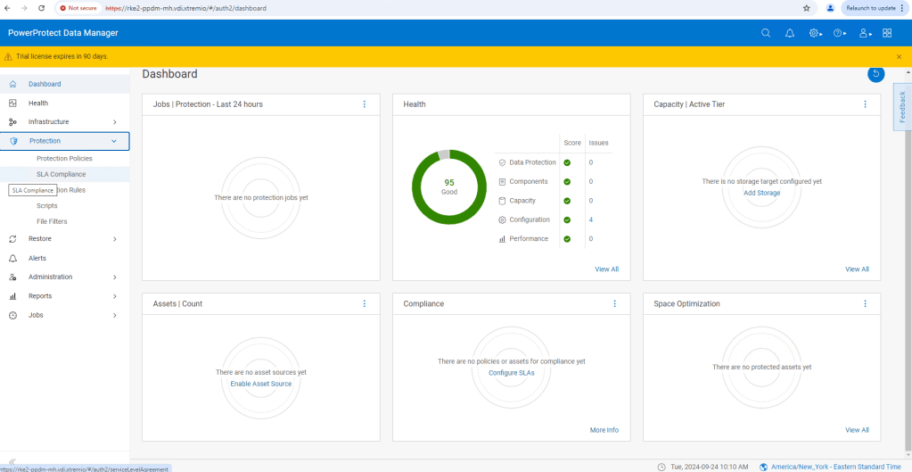
Browse to the FQDN address we configured, in this case https://rke2-ppdm-mh.vdi.xtremio. After ignoring the warning, you are then presented with the ‘New Install’ wizard. Click next and accept the EULA. Select the 90 Day Eval license, and then set up your new password.
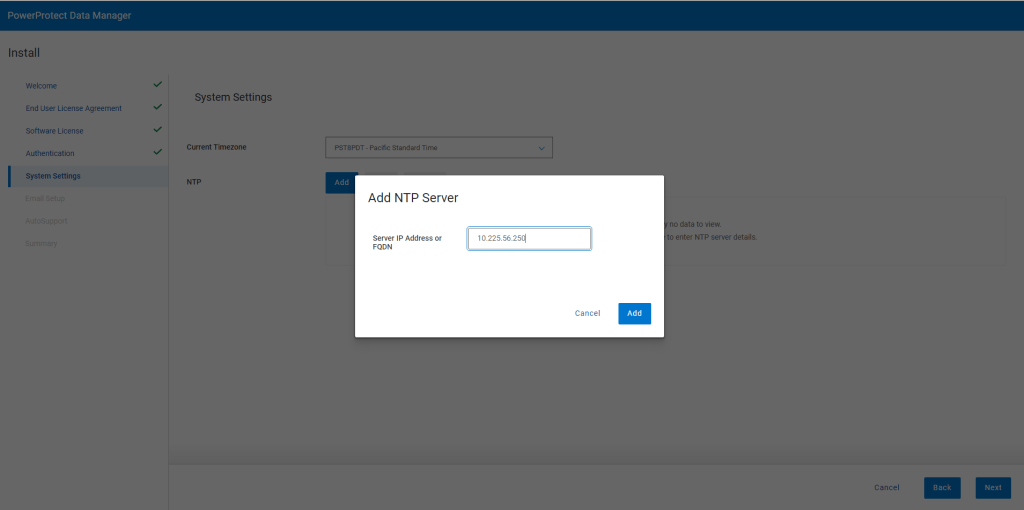
When prompted set your timezone and NTP server.
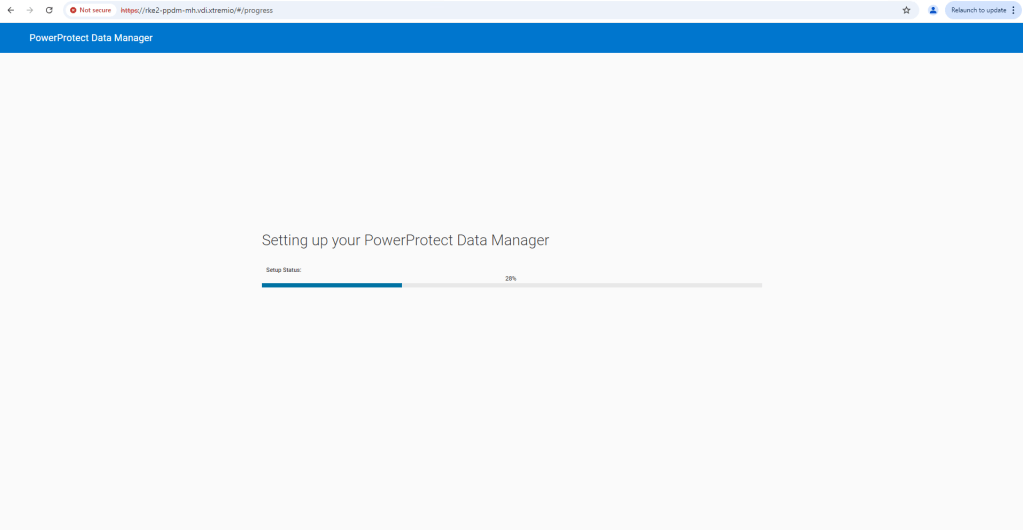
As this is a demo, I will skip over the Email setup, and proceed straight to the ‘Summary’ page. Click ‘Done’ and PPDM will start to configure the system based on the settings provided.
When complete, the main logon page will refresh. Use the password you previously configured and logon as Admin user.
Click ‘Continue’
Congratulations!! In you go. We will leave PPDM for now and proceed to Step 2, to configure APEX Protection Storage (DDVE). In Step 3, we will then link both together.
Again, make sure NTP and forward/reverse DNS are configured properly. The system installer will check if there is a problem and the installation process will fail. I will deploy to the same vSphere cluster, but obviously this isn’t a hard requirement.
Give the VM a name, I usually mirror the FQDN and assign it to a cluster or host. Ignore the certificate warning and click ‘Next’.
Next select your configuration type, this will preconfigure the VM based on the workload use case. This is for a demo, so we will pick one of the smaller configurations, I went with the 16TB option, just because I have lots of capacity in the lab. The 8GB option will be absolutely fine for demo purposes also. Click next and select your storage target.
Select your virtual networks, by default the OVA template will configure 2 interfaces and you can add up to 9 after configuration. For this demo I will only end up using the single interface, the second will be used in another post when we talk about cross protection storage replication.
Double check everything looks OK and then click ‘Finish’. The OVA will start to deploy, as with the PPDM install, you can monitor the status in the vSphere progress bar.
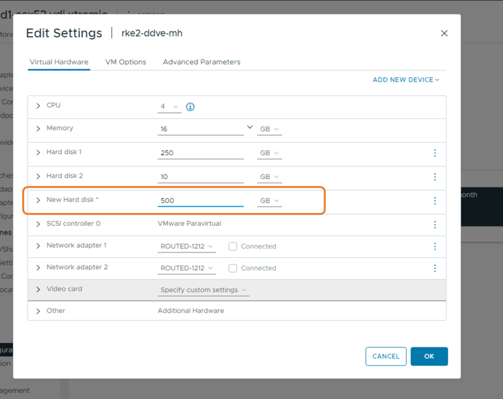
3. Add Storage before first boot
Before we power up the VM, we need to add storage. We can add a minimum of 250GB, but I will add 500GB of useable storage. On the VM, Right click, then ‘Edit Settings’ and add a 3rd disk. I will run through all steps in the video also.
3. Boot Virtual Machine and Launch Virtual Console
DDVE will take a couple of minutes to intialise, so be patient!
4. Initial configuration
NIC 0, is configured for DHCP, so technically you should be able to browse via 443 to the IP address allocated via DHCP, in order to do the initial configuration. I am going to assume that you may not have DHCP in your environment, so we will configure via the command line VM console.
Log on using the default username/password combination of sysadmin/changeme. Scroll through the EULA ( warning its long !), then enter and confirm the new sysadmin password. For now we won’t configure the security officer credentials. Select no when prompted to configure using the GUI.
Configure Network at this time : Yes
Use DHCP for hostname, domainname, default gateway and DNS? No
Hostname: Enter the FQDN. Make sure to get this right as the installation will fail otherwise
Domainname: Enter your domain name
Ethernet port ethV0: Enable Yes
Use DHCP on Ethernet port ethV0: No
Enter IP address
Enter the netmask
Ethernet port ethV1: Enable No
Default gateway:
IPV6 Default Gateway: None
DNS Servers: Enter the list of DNS servers
Do you want to save these settings: Save
Configure eLicenses: No
Configure system at this time: No
Configuration complete!
5. Create File System
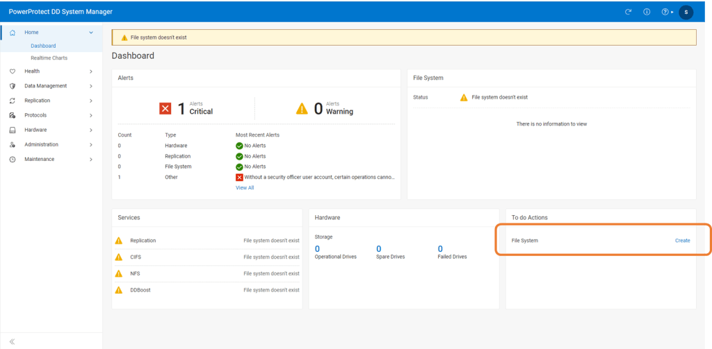
Now log into DDVE ( APEX Protection Storage), via the newly configured address. We should really use the FQDN to ensure it is working.
In the ‘To Do Actions’ section click on ‘Create’, in order to initiate the File System wizard.
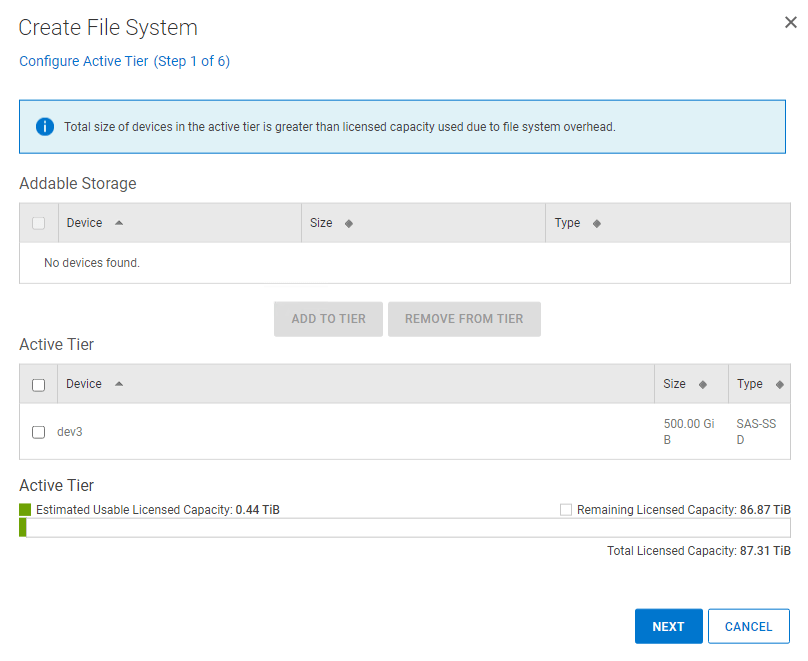
Then Click on create.
Step through the wizard. Select the 500GiB drive we have presented as the dev3 device and add to the Active Tier. Click Next and skip the Cloud Tier and the Cache Tier section. We will revisit this in a future post.
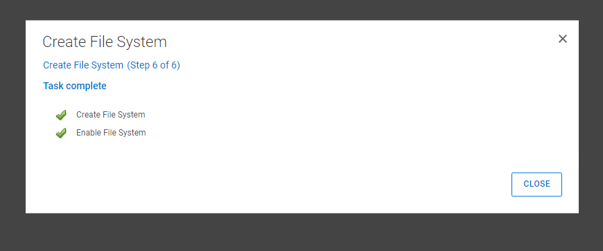
Run the assessment, This will take a couple of minutes. As this is a test environment you can skip if you wish. If you have the time I would recommend it though. Click ‘Next’ and then ‘Finish’.
After a few minutes the File System creation will have finished.
6: Check Protocol Status and Enable DD Boost
Enable DD Boost if not already done so. Navigate to Protocols -> DD Boost
Step 3: Integrate APEX Protection Storage with PPDM
Now we have APEX Protection stood up, the next step is to integrate with PPDM and add as an asset source. This is a very straightforward process.
1. Log back into PPDM
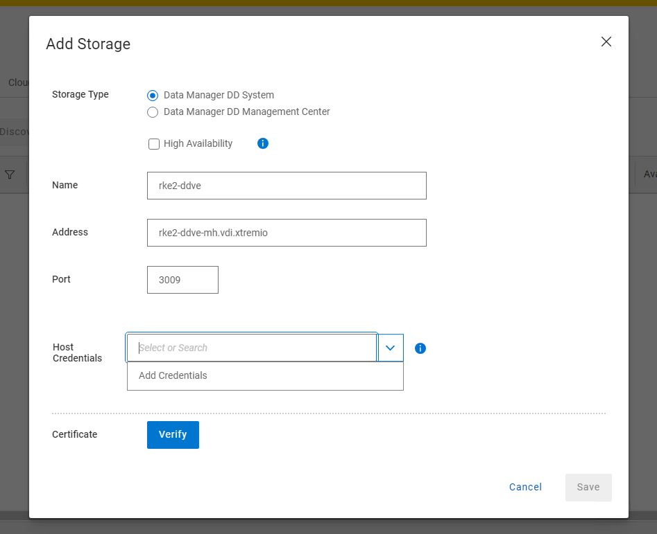
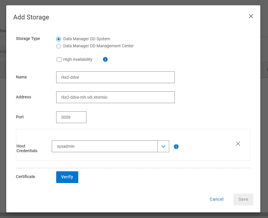
2. Navigate to the Infrastructure, then Storage tab and Add Storage
3. Add Storage and Credentials
I have used the FQDN as best practice. Leave the discovery port as 3009. As this is a fresh install you will need to create a new host credential. This is the sysadmin username/password combination of the APEX protection Storage device we have just deployed.
Click Verify and Save.
After a few moments the discovery job should kick off and the DDVE storage device will be discovered.
Job done….. In the next post we revert back to our RKE2 environment and configure the CSI driver, present some persistent storage via PowerScale and create some demo applications. Once that is complete, we will configure the PPDM environment to discover our K8S namespaces and PVC’s, apply a protection policy and demo some failover scenarios.
Video Demonstration
DISCLAIMER
The views expressed on this site are strictly my own and do not necessarily reflect the opinions or views of Dell Technologies. Please always check official documentation to verify technical information.
Late last year I did a series on protecting EKS based cloud workloads in AWS using DDVE and PPDM, or to give its official term, Dell APEX Protection Storage for AWS. This was a real from the ‘ground up’ exercise and it assumed that no infrastructure existed, so we covered off the setup of the VPCs, Security groups, deployment of PPDM and DDVE in the cloud, AWS EBS CSI driver installation and finally a workload failover demonstration. The complete end to end experience.
This time around, I’ve decided to get my head out of the clouds and get back to ‘terra firma’, and do a series based completely with on-premise in mind. Again though, from the ground up. We will build out the RKE2 Kubernetes environment leveraging SUSE Rancher , deploy the Dell CSI driver for Dell PowerScale, create some sample container workloads bound to Persistent Volume Claims (PVC’s), stand up and configure a fresh new install of PPDM and DDVE, add our RKE2 cluster as a data source to PPDM and well… you get the picture… the full story end to end.
So let’s get started.
Deploy SUSE Rancher on Docker
SUSE Rancher is an open-source software platform designed to manage and deploy Kubernetes clusters at scale. It provides a comprehensive set of tools for DevOps teams to run containerized workloads while addressing the operational and security challenges of managing multiple Kubernetes clusters across various infrastructures. For the purposes of this demonstration it is extremely easy to spin up a fully functioning version of SUSE Rancher running on Docker. I will build on the architectural diagram as we go, but at its very simplest we will be deploying:
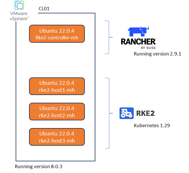
SUSE Rancher v2.9.1. Deployed on a docker container running Ubuntu Server 22.0.4LTS. This is really very straightforward. Note, the docker based setup is for test and POC purposes only and is not supported in production environment. The link to the official documentation is here.
RKE2 running Kubernetes v1.29.8
SUSE RKE2 is an enterprise-grade Kubernetes distribution, provided by SUSE, that is designed to provide a secure and reliable foundation for containerized workloads. It is built on the lightweight, CNCF-certified RKE2 Kubernetes distribution, which is optimized for security and compliance. SUSE RKE2 offers a streamlined installation process and simplified operations, making it suitable for on-premise, hybrid, and edge environments. We will use Rancher to orchestrate the installation and initial configuration of our RKE2 Kubernetes environmenet.
Finally, In my lab scenario we will deploy everything in a VMware vSphere environment which is currently running version 8.0.3. Note that Rancher can directly integrate with vCenter directly via API and provision resources directly into the vSphere managed environment, in a cloud like operating model. For our demo, whilst using vSphere, we will not be using the cloud model, but rather our target Ubuntu virtual machines will appear as bare-metal to both Rancher and RKE2 when deployed. This will become a little clearer during the demonstration video.
Note: Before we get started, please save yourself a world of pain and make sure you have NTP and forward/reverse DNS configured everywhere in your environment..
So let’s get started. As you see in the above diagram we have our vSphere environment and 4 Vanilla servers running Ubuntu 22.0.4. I have provisioned each with 64GB of memory, 4 vCPU’s and a single 800GB Hard Disk. Most definitely overkill, but I am lucky enough to have the resources in my lab. Everything is running on a routable flat network connected to a simple vswitch, so nothing fancy going on here.
1. Install Docker your Target Rancher Server.
On the host you wish to deploy Rancher on, execute the following to install Docker. Make sure the version of docker is compatible with the Ubuntu server and Rancher version. Link here. In my case it is version 26.0 according to the support matrix.
curl https://releases.rancher.com/install-docker/26.0.sh | sh
2. Verify docker has installed properly.
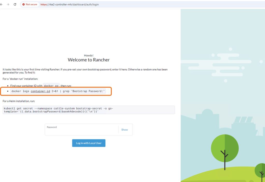
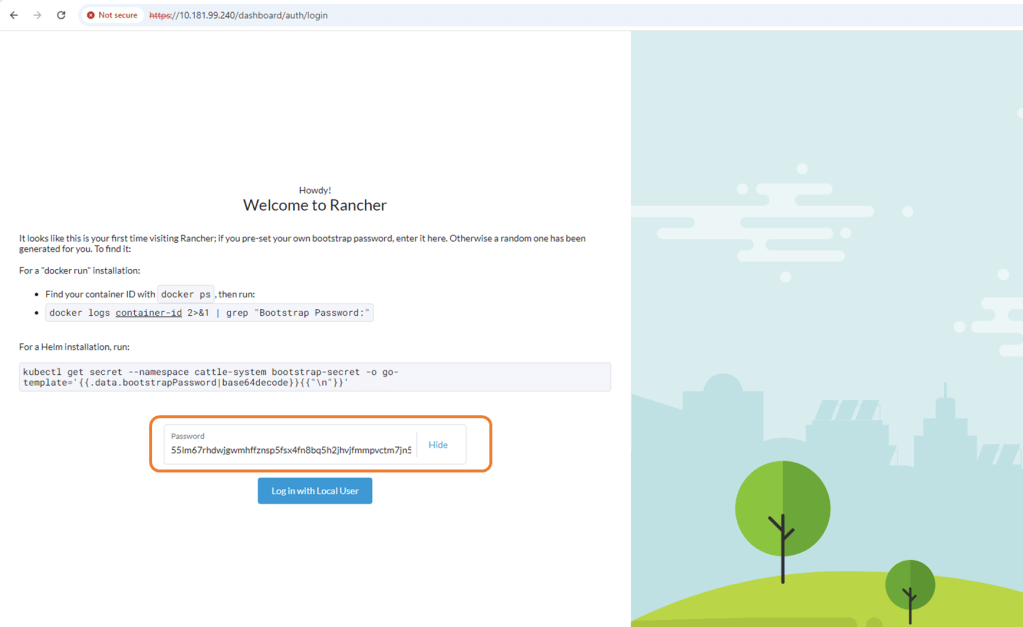
3. Install the Rancher Docker Container with rancher generated self-signed certificate.
Copy the bootstrap password use to logon to Rancher for the first time.
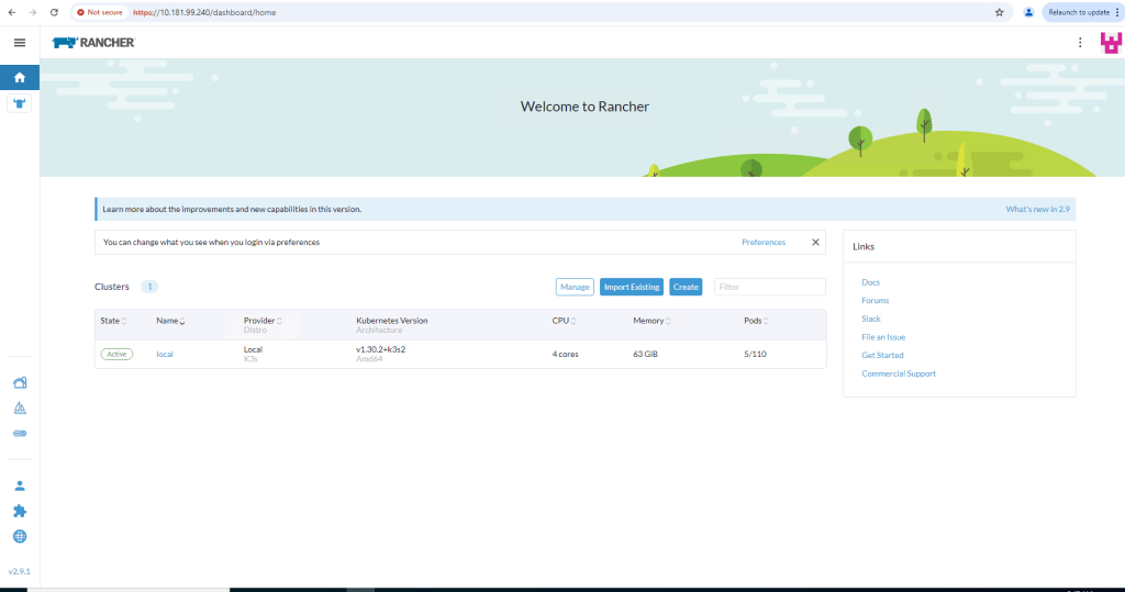
Configure new password and accept EULA.
Log in to Rancher for the first time.
Deploy RKE2 Kubernetes cluster using Rancher
Now that we have Rancher up and running, it really is very straightforward to get a 3 node fully functioning RKE2 cluster up and running. I’ve covered off all the required steps in the accompanying video also.
Step 1: Create Cluster.
Navigate to the ‘Cluster Management’ tab and from there, click ‘Create’
Next up, click on the custom tab and not the VMware vSphere button. Whilst we will be deploying on a test vSphere environment, we will not be leveraging the vSphere integrations with Rancher. We will be emulating a ‘Bare-Metal’ on premise types installation.
Configure the cluster, Give it a cluster name such as ‘ppdm-demo’. I have accepted all the defaults including the CNI integration Calico but I have stepped back one iteration of K8S version – v1.29.8. Leave the default cloud provider as is and click ‘Create’
My test cluster is going to consist of 3 hosts, all assigned etcd, control plane and worker node functionality. We will need 3 for a quorum. Again this process is very easy. To make life easier and as this is a demo environment then check the ‘Skip the TLS verification’ box under the registration command. Copy the Registration command
Open a putty session to our 3 target hosts and paste the copied Registration Command. Note: you may need to amend ‘sudo’ to the start of the command.
Rancher starts the process of deploying RKE2 to the 3 nodes.
Step 2: Monitor provisioning Status
Navigate to the ‘Provisioning Log’ tab on the Rancher Cluster Management tab. You should see the deployment progress.
Step 3: Validate the deployment
This can be done both via the Rancher GUI and the embedded Kubectl function within Rancher. In the next post we will set up our management machine with Kubectl installed and permissions attached to allow us to talk directly to the cluster via the API. For now though we will leverage Rancher directly.
Via the GUI, navigate to the ‘Machines’ tab to verify the cluster health
Next Navigate back to the Cluster Dashboard. You should see our new cluster on the left hand pane. You can see a graphical representation of our active Pods, workloads, apps etc. At the moment we have nothing configured. On the top right hand corner of the GUI the ‘Kubectl Shell’ button sits. Click on this to open the shell for the cluster
Click to open the shell and verify the node status using the ‘kubectl get nodes’ command and examine any running Pods in all available namespaces using the ‘kubectl get pods -A’ command
Video Demo
Attached, video run through of the above.
Up Next
Now we have Rancher installed, next up vanilla install of Dell Power Protect Data Manager and Dell Data Domain Virtual Edition. Once that is up and running , we will integrate with Rancher, configure some sample workloads and demo some recovery scenarios.
DISCLAIMER
The views expressed on this site are strictly my own and do not necessarily reflect the opinions or views of Dell Technologies. Please always check official documentation to verify technical information.
‘Traditional network fabrics are ill equipped to deal with the performance and scale requirements demanded by the rapid emergence of Generative AI (Gen-AI)’.
That’s the common refrain… but hang on a minute, my current network infrastructure supports every other workload and application so what’s the problem? In fact my current infrastructure isn’t even that old! Why won’t it work?
To understand why this is the case we need to take a quick 10000 foot overview of what we typically have in the Data Center, then let’s layer some AI workload ( GPU’s everywhere!) on top and see what happens. Health warning… This isn’t an AI blog, like everybody else I am learning the ropes. Out of curiosity, I was interested the above statement, and wanted to challenge it somewhat to help me understand a little better.
First things first, a brief synopsis of the Enterprise Data Center fabric in 1000 words or less an 2 diagrams. I do make the bold assumption, that those reading this blog, are at least familiar with the basic spine/leaf fabrics that are pretty ubiquitous in most enterprise Data Centers.
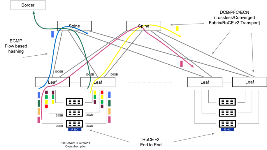
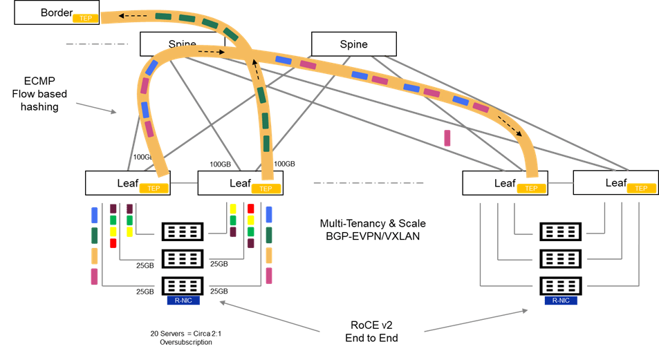
The Basic Spine/Leaf Topology
I do like a diagram! Lots going on in the above, but hopefully this should be relatively easy to unpack. There is quite a bit of terminology in the following, but I will do my best to keep this relatively high level. Where I have gone a little overboard on an terminology PFC, ECN, ECMP, i have done so with the intent on following up on the next post, where I will overview some of the solutions.
Typically we may have:
Many Heterogeneous flows and application types. For example, Web Traffic bound to the Internet via the network border (Green Flow), Generic Application Client Server Traffic inter host (Purple Flow) and perhaps loss/latency sensitive traffic flows storage, real-time media etc. (Yellow Flow)
These flows generally tend to be short lived, small and bursty in nature.
The fabric may be oversubscribed at of a ratio of 2:1 or even 3:1. In other words, I may have 20 servers in a physical rack, served by 2 Top of Rack Switches (TOR). Each server connecting at 25Gbps to each TOR. (Cumulative bandwidth of 500GB). Leaf to Spine may be configured with 2 X 100Gbps, leaving the network oversubscribed at a ratio of circa 2.5:1.
Intelligent buffering and queuing may be built in at both the software and hardware layers to cater for this oversubscription and mitigate against any packet loss on ingress and egress. One of the key assumptions here, is that some applications are loss tolerant whilst others are not. In effect, we know in an oversubscribed architecture, we can predictably drop traffic in order to ensure we protect other more important traffic from loss. Enhanced QoS (Quality of service) with WRED (Weighted Random Early Detect), is a common implementation of this mechanism.
Almost ubiquitously, ECMP (Equal Cost Multipath Routing), which is a hash-based mechanism of routing flows over multiple equally good routes is leveraged. This allows the network, over time, load balance effectively over all available uplinks from leaf to spine and from spine to leaf.
The fabric can be configured to enable lossless end to end transmission to support loss intolerant storage-based protocols and emulate the capabilities of Fiber Channel SAN and InfiniBand leveraging Data Centre Bridging (DCB), Priority Flow Control (PFC) and Explicit Congestion Notification (ECN).
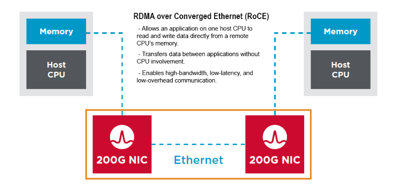
RDMA (Remote Direct Memory Access) capability can be combined with lossless ethernet functionality, to offer an end-to-endhigh performance, lossless, low latency fabric to support NVME and non-NVME capable storage, as well as emerging GPUDirect Storage, distributed shared memory database and HPC/AI based workloads. This combined end-to-end capability, from server to RDMA capable NIC, across the fabric, is known as RoCE (RDMA over Converged Ethernet), or in its most popular iteration, RoCE v2 (routable RoCE). ( Spoiler: This will be part of the solution also!)
What about Scale and Multitenancy?
In general, enterprise grade fabrics require more than just spine/leaf to deliver feature richness in terms of scale, availability and multi-tenant capability in particular. Enterprise fabrics have evolved over the last number of years to address these limitations primarily leveraging BGP-EVPN VXLAN. Whilst considerably beyond the scope of this post, this family of features introduces enhancements to the standard spine-leaf architecture as follows:
Scale and Availability leveraging VXLAN
VXLAN (Virtual Extensible LAN) as opposed to VLANs. Unlike traditional VLAN networks, which are constrained to circa 4096 VLAN’s, VXLAN can theoretically scale up to 16 million logical segments.
Layer 2 adjacency across the fabric with VXLAN/VTEP tunnelling and distributed anycast gateway. VXLAN encapsulates layer 2 frames within UDP and tunnels payload across the network. Distributed gateway makes the networks IP gateway available across the entire fabric. This feature is a fundamental enabler to allow virtual machine IP address preservation, in the event of VM machine mobility across the fabric (e.g. VMware vMotion)
Failure domain segmentation via Layer 2 blast radius isolation: The Layer 2 over layer 3 VXLAN tunneling technique limits the propagation of Spanning-Tree L2 domains to the local TOR. Without such a technique there is no scalable mechanism to limit the fault propagation on one rack, polluting the entire network.
Multitenancy with MP BGP EVPN ( Multi-Protocol Border Gateway Protocol)
As an extension to the existing MP-BGP, MP-BGP with EVPN, inherits the support for multitenancy using the virtual routing and forwarding (VRF) construct. In short, we can enforce Layer 2 and Layer 3 isolation across individual tenants, whilst leveraging the same common overlay fabric. This has made this technique very popular when deploying cloud networks, both public and private.
So, I’m sure I have missed a lot and of course I have skirted over masses of detail, but broadly the above is representative of most Enterprise Data Centers.
Evolution to Support Scale Out Architectures and AI
So first things first, all is not lost! We will see this in the next post, I have alluded to the above that many of the existing features of traditional ethernet can be transposed to an environment that supports GEN-AI workloads. Emerging techniques to ‘compartmentalise’ the network into succinct areas are also beneficial…again we will discuss these in the next post.
What happens the Traditional Fabric when we load up GEN-AI workload on top?
So let’s park the conversation around rail architectures, NVIDIA NVLINK, NCCL etc. These are part of the solution. For now, let’s assume we have no enhancements, neither software or hardware to leverage. Let’s also take this from the lens of the DC Infrastructure professional…. AI is just another workload. Playing this out, and keeping this example very small and realistic:
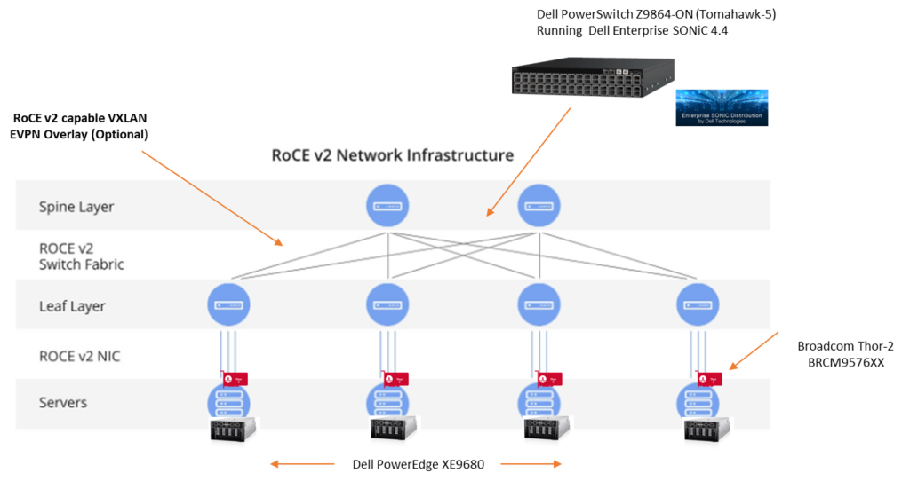
4 Servers dedicated for AI workload (learning & Inferencing). Let’s say the Dell XC 9680. Populated with our favorite GPU’s from NVIDIA, say 8 per server.
Each GPU has dedicated PCIE NIC speed of 200GB.
I’m a clever network guy, so I know this level of port density and bandwidth is going to blow my standard oversubscription ratio out of the water, so I’m ahead of the game. I’m going to make sure that I massively up the amount of bandwidth between my leaf layer and the spine, to the point be I have no oversubscription. I am hoping that this will look after this ‘tail latency’ requirement and Job Completion Time (JCT) metrics that I keep hearing about. I have also been told that packet loss, is not acceptable… again .. no problemo!!! My fabric has long since supported lossless ethernet for voice and storage…
so all good… well not really, not really at all!
Training and Inferencing Traffic Flow Characteristics:
To understand why throwing bandwidth at the problem will not work, we need to take a step back and understand the following:
AI Training is associated with a minimal amount of North-South and a a proliferation of East-West flows. Under normal circumstances this can put queuing strain on the fabric, if not architected properly. Queuing is normal, excessive queuing is not good and can lead to packet delay and loss.
AI training is associated with a proliferation of monolithic many to many (M:M) and one to many (1:M) Elephant Flows. These are extremely large continuous TCP flows, that can occupy a disproportionate share of total bandwidth over time, leading to queuing, buffering, and scheduling challenges on the fabric. This is as a result of the ‘All to All’ communication between nodes during learning.
The Monolithic nature of these flows leads to poor distribution over ECMP managed links between spine and leaf. ECMP works best when flows are many, various and short-lived.
If we attempt to deploy an AI infrastructure to deliver Training and Inferencing services on a standard Ethernet fabric, we are likely to encounter the following performance issues. These have the capability to effect training job completion times by introducing latency, delay and in the worst-case loss onto the network.
Job Completion Time (JCT) is a key metric when assessing the performance of the Training phase. Training consists of multiple communications phases, and the next phase in the training process is dependent on the full completion of the previous phase. All GPU’s have to finish their tasks, and the arrival of the last message effectively ‘gates’ the start of the next phase. Thus, the last message to arrive in the process, is a key metric when evaluating performance. This is referred to as ‘tail latency’. Clearly, a non-optimised fabric where loss, congestion and delay are evident, has the capability of introducing excessive tail latency and significantly impacting on Job Completion Times (JCT’s).
Problem 1: Leaf to Spine Congestion (Toll Booth Issue)
So we have added lots of bandwidth to the mix, and indeed we have no choice, but in the presence of Monolithic long-lived flows and b) the inability of ECMP to hash effectively, then we have the probable scenario of flows concentrating on a single, or subset of uplinks from Leaf to Spine. Invariably, this will lead to the egress switch buffer, on the leaf filling and WRED or tail drop ensuing. Congestion will of course, interrupt the TCP flow and will have a detrimental effect on tail latency. This is the ‘Toll Booth’ effect where many senders are converging on a single lane, when other lanes are available for use.
The non variable and long lived nature of the flow ( Monolithic), combined with the inability of ECMP to hash effectively ( because it depends on variability !) is a perfect storm. We end up in a situation where a single link between the Leaf and Spine is congested, even when we have multiple other links are underutilised, as if they didn’t exist at all! We have added all this bandwidth, but in effect we aren’t using it!
Problem 2: Spine to Leaf Congestion
Of course, the problem is compounded further one hop further up the network. ECMP makes a hash computation at the spine switch layer also, and chooses a downlink based on this. The invariability or homogeneous nature of the hash may lead to a sub-optimal link selection and the long-lived nature of the flow will then compound the issue, leading to buffer exhaustion, congestion and latency. Again, we may settle on one downlink and exhaust that link, whilst completely underutilise others.
Problem 3: TCP Incast – Egress Port Congestion
Finally, we potentially face a scenario created by a ‘Many to 1’ communication flow (M:1). Remember the M:M traffic flows of the learning phase are really all multiple M:1 flows also. This can occur on the last link towards the receiver when multiple senders simultaneously send traffic to the same destination.
Up next
So clearly we have zoned in on the ills of ECMP and its inability to distribute evenly flows across all available uplinks towards the spine and in turn from the spine towards the destination leaf. This is a per flow based ‘hash’ mechanism (5 Tuple) and generally works very well in a scenario where we have:
A high percentage of east-West Flows, but still a large relevant proportion of North-South, to Internet, SaaS, DMZ etc.
Many heterogenous flows that are short lived. In other words, we have many senders and many receivers. Over time, this variance, helps the ECMP hash evenly distribute across all available uplinks, and we end up with a balanced utilisation.
A minimal amount of ‘All to All’ communication, bar traditional multicast and broadcast, which are handled effectively by the network.
Unfortunately, AI workloads are the antithesis of 3 characteristics, outlined above. In the next post we will overview some Dell Switching Platform enhancements that address these shortcomings, in addition to some clever architectural techniques and intelligence at the server source ( e.g. NVIDIA NCCL library, Rail Topology enhancements etc.)
Stay Tuned!
DISCLAIMER
The views expressed on this site are strictly my own and do not necessarily reflect the opinions or views of Dell Technologies. Please always check official documentation to verify technical information.
PPDM 19.17 dropped earlier today. Pick of the a pretty big bunch for me were the storage array integrations.
Storage Direct with PowerStore enhancements.
Storage Direct capability has been around with PPDM for a while now offering PowerStore platform support. (Release 19.14, which dropped in mid 2023). It achieves this by leveraging the DDBoost protocol (Data Mover) directly within a container in the PowerStore node. The original release only offered the capability crash consistent backup support however.
The new release of PPDM 19.17 adds some significant enhancements in terms of Application Consistent Backup support (the ability to quiesce and unquiesce the applications/databases, to ensure the full integrity of the backup). It does this by adding the capability to leverage pre and post scripts that directly allow PPDM to interact with the backend application. This also includes Meditech support but can be any generic application/database. I hope to provide a demo of this in a future post so stay tuned. (Link to brand new Meditech with PPDM/Powerstore attached in the links section below)
Storage Direct with PowerMax
What really has caught my eye in this release, is the addition of PowerMax Storage Direct support.
Digging under the hood, this is vastly different on how the first iteration of Storage Integrated Data Protection that supported VMAX and XtremIO was implemented, that leveraged the proprietary vDisk protocol to point to a DataDomain target over FC. It served its purpose at the time, but let’s just say it was rather complicated, and didn’t scale too well.
Fast forward, and of course we have StorageDirect with PowerStore (above), which is a significant enhancement in TCO, via placing the data mover capability directly within a container in the PowerStore appliance itself. Leveraging DDBoost over IP versus a dependency on FC connectivity.
StorageDirect with PowerMax, steps this forward again, by leveraging an external Data Mover architecture, decoupling this task from the physical array itself. This is important when we consider the positioning of PowerMax, in terms of the mission criticality of the workload. All other things being equal, we want to take this load away from the array and let it do what it does best, store mission critical data. By creating this proxy architecture, of course we can now scale-out in lockstep with the requirements of the array and in line with SLA and recovery objectives. Without externalising the proxy architecture, this would be difficult to achieve. Initially the proxy will be running inside a VM on ESXi, but given that it is external, then eventually perhaps this can be in the cloud, on other hypervisor platforms, bare-metal etc.
As of this release, only the latest generation PowerMax, 2500/8500 series models are supported, offering some key benefits including but not limited to:
Block Storage.
Externalised Proxy architecture removes any overhead of PowerMax CPU/Cache etc.
Scale Out Architecture with multi stream capability allows you to scale and grow as needed (More detail on this below!)
Simplified and automated workflow integration, execution and orchestration via PPDM.
Full and Synthetic backup support.
Automated pre/post scripting for application consistent backups. e.g mission critical Oracle, EPIC, MSSQL backups requiring six nines availability and data consistency.
Better integration with other formats of DDoS, including DDVE in the Cloud and on Premise ( Note: DDVE has been rebranded everywhere as Apex Protection Storage)
Multiple PowerMax arrays supported via Unisphere.
Support for common features including Retention Locking, Cloud Tiering, Replication.
Architectural Overview
So how does this work? There is quite a bit of detail in the attached diagram, but I will try and step through it as best I can ( Tip: I have attached in gallery format, so double-click and you should be able to expand)
All the above is fully orchestrated by PPDM manager, bar the zoning and masking and presentation of storage from the PowerMax array to the ESXi hosts where our Proxy Block Volume Data Movers reside and some initial pre-steps on the array itself. There is a good reason for this in that the intermediary FC switch could be Cisco, Brocade etc., so it likely to be very customer bespoke. Additionally, the customer may want to be judicious in what hosts are presented. So for now, that’s a task outside the PPDM workflow.
In short:
Connect PPDM to the PowerMax Storage array, either via the embedded Unisphere application on the array itself or an external Unisphere host running on windows for instance. Both are supported.
Create a backup storage group on PowerMax, present this to the ESXi hosts where our Proxy Data Movers will be deployed and configured. This is the masking and zoning piece that we talked about above.
Install the Proxy Data Mover/Block Volume Data Mover as a Protection Engine. The ability to deploy a protection engine has been around a while, but you will see in the new 19.17 UI the capability to add a ‘Block Volume’ Protection type which is limited to PowerMax. Block Volumes are obviously supported with PowerStore, but remember the DataMover is directly embedded in a container on the array. This step directly pushes a DataMover embedded within a virtual machine directly to an ESXi host, we can deploy multiple proxies in this fashion as we scale out.
For our application host data that we wish to protect, there is a good chance that this may be a mission critical database. The initial release supports application consistent backup capability, i.e. the ability to quiesce and unquiesce the database, before we orchestrate a backup snapshot. To do this we deploy an FSagent as per normal, but we now have the ability to push pre and post scripts via the agent to the application database host to stop read/writes and resume post snapshot.
Use PPDM to fully orchestrate the backup – where the magic happens:
Schedule the backup in PPDM as normal, PPDM then automatically discovers everything in PowerMax. Storage groups etc.
Initiate the backup. PPDM executes the scripts via the FSagenet to freeze writes. After the freeze then we create a snapshot on the array ( the Volume we created in the pre-steps). Post the snapshot, we then automatically initiate the post script, to start writing to the database/application again. This is generally a very fast process.
Now we can protect the snapshot by automatically presenting this storage to the ESXi/Data Mover hosts (1 or multiple dependent on what we have)
Initially the volume/size of the backup is going to being very large, this gets pushed to our Data Domain, but in chunks of 64GB, streamed in batches. this makes the whole process extremely efficient and allows us to scale out by adding multiple proxies and scale up based on available bandwidth presented to each proxy. The more proxies I have and the more bandwidth, the faster I can send my chunks of data. From initial testing 4 seems to be the sweet spot with 25GB backend connectivity to the array.
Of course for iterative backups, the data may have changed very little. The proxy caters for this, by doing a bitmap calculation looking for changed blocks and only transferring these via DDboost to the target Data Domain.
Links to more Information
Nice whitepaper by my colleague Vinod Kumaresan on Meditech, PPDM and Powerstore integration here
Another great blog by Vinod on PowerMax integration with PPDM 19.17 here.
Partner Link to Recorded Knowledge Transfer ( partner logon required !)
3 part video series on Powermax integration with PPDM here
Release notes here. nice page overviewing new features.
DISCLAIMER
The views expressed on this site are strictly my own and do not necessarily reflect the opinions or views of Dell Technologies. Please always check official documentation to verify technical information.
Quite a bit to unpack here, but I’ll do my best. First things first though, it is becoming increasingly clear that network fabrics are key components to the performance of AI Compute Clusters. AI Fabrics demand special requirements such as low latency, lossless performance and lots and lots of bandwidth. The massive parallel data and application processing requirements of GenAI are driving, this exponential requirement overhead on front and back end fabrics. What was once really just the purview of niche and proprietary InfiniBand HPC environments, is quickly becoming center stage for all enterprises, together with a clear shift towards Ethernet.
Bottom Line GPU’s are getting larger and demand more bandwidth, so the networking stack must adapt to meet these new requirements. The amount of data flowing from GPU to GPU and server to storage is growing exponentially. The other point to note is that these are end to end requirements, from server, to NIC, to Switch , to the overarching Networking Operating System that knits all these components together. In order to deliver a performant end to end solution, we need an end to end approach. Enter the Dell AI Fabric…. and its foundation Dell AI fabric Infrastructure.
So what was announced?
I’ll dig into the deep weeds around topics such as Lossless fabric enablement, Intelligent load balancing/routing (plus cognitive routing. Mentioned by Michael Dell at the DTW keynote yesterday!) and end to end compute layer integration with RoCEv2, amongst others in future posts. For now though let’s overview some highlights, with a somewhat deeper nod to key new features….. As usual, I have attached some links to key content and other blogs….
So what do these new enhancements to the integrated fabric look like?
Enables the next generation of unified data center infrastructure with 64 ports of 800GbE switching and routing. It can also be used as a 100/200/400 switch via breakout, allowing for a maximum of 320 Ports. Twice the performance of the current generation PowerSwitch.
Six on-chip ARM processors for high-bandwidth, fully-programmable streaming telemetry, and sophisticated embedded applications such as on-chip statistics summarization.
Unmatched power efficiency, implemented as a monolithic 5nm die.
RoCEv2 with VXLAN
Adaptive Routing and Switching
Cognitive Routing support in hardware (delivered by future software release)
I’ve missed loads more but… as promised this isn’t a datasheet. Of course here is the link to the new datasheet.
Z9864F-ON Rear View
Why this matters.
A couple of reasons:
Backend Fabrics consume massive bandwidth. Design Goal #1: The higher the radix of your switch fabric the better. You want to strive for flat and dense connectivity where at all possible. This is a key design goal. In other words, the ability to pack in as much connectivity, at line rate, without having to go off fabric or introduce multiple tiers of latency inducing switches. The Dell Z9864F-ON with Enterprise SONiC 4.4, can connect up to whopping 8K GPU nodes in a single two-tier 400GB fabric. Expanding from the standard 2K in a 2 tier topology from the previous Tomahawk 4 based platform.
Adaptive Routing and Switching (ARS). This is blog worthy topic in its own right but for now the bottom line: Design goal number 2: high throughput with low latency. AI/ML traffic flows, especially in the backend are characterised by a proliferation of East-West, machine to machine, GPU to GPU flows. AI/ML flows are also characterised by buffer and path filling Elephant flows, which if not managed properly can introduce loss and latency. These last two terms signal the death knell to AI/ML fabric performance. We need a mechanism to dynamically load balance across all available paths, to minimise the ill effects of elephant flows. Adaptive Routing and Switching (ARS) dynamically adjusts routing paths and load balances based on network congestion, link failures, or changes in traffic patterns. This ensures that traffic is efficiently routed through the network. So for those wondering, you may see the term Dynamic Load Balancing (DLB) used here instead. Both DLB and ARS can be used interchangeably.
Cognitive Routing brings this path sharing intelligence one step further. Broadcom introduced Cognitive Routing in their industry-leading Tomahawk 5 chipset, the chip architecture underpinning the Z9684-ON. It builds upon the adaptive routing functions present in previous generations of Tomahawk products, emphasizing the performance needs of Ethernet-based AI and ML clusters. Supported in hardware as of this platform release, the true capability of this feature will be unlocked via future SONiC releases, post 4.4. For a lot more depth on this topic and how it works under the hood, follow the link to the following great post by Broadcom.
Bottom line… a higher radix, higher bandwidth switch fabric, denser connectivity with multiple line rate high bandwidth switch ports , and intelligent flow and congestion aware load balancing across all available paths at both a hardware and software layer leads to maximised bandwidth utilisation, minimised loss and reduced average and tail latency. Simple….net result…. enhanced job completion times and more responsive inferencing.
RoCEv2 with VXLAN
End to End RoCEv2 over L2 and Layer 3 networks have been around for a while with Dell Enterprise SONiC. They were designed originally for to meet the increasing popularity of converging storage over existing ethernet fabrics, but are now really gaining traction in other settings such as AI/ML backend and frontend networking.
Very long story short, traditional ethernet sucks when transporting storage or any loss intolerant application. Storage is loss intolerant, hence the rise of ‘lossless’ fabrics such as Fiber Channel. Ethernet on the other hand is a ‘lossy’ fabric, which relies on the retransmission capabilities of TCP/IP. In order to square the circle, and make ethernet lossless then a couple of QoS feature enhancements were introduced at the switch level over the past decade, including but not limited to the following:
Priority Flow Control (PFC) – provides congestion management by avoiding buffer overflow and achieves zero-packet loss by generating priority-based pause towards the downstream switch.
Enhanced Transmission Control (ETS) – allocates specific bandwidth to each class of service to prevent a single class of traffic hogging the bandwidth.
Explicit Congestion Notification (ECN) – marks packets when the buffer overflow is detected; end hosts check the marked packet and slow down transmission.
Data center bridging protocol – operates with link layer discovery protocol to negotiate QoS capabilities between end points or switches.
In layman’s terms, ethernet now had a mechanism of priortising storage flows via DSCP and ETS, pause sending packets to the next switch when it detects congestion and telling its neighbors when its buffers are about to fill (PFC and ECN), and agreeing a common language between switches in order to make sure everybody understands what is happening (DCB). Hey presto, I can send storage traffic from switch to switch without loss….
On the server side, in order to drive low latency outcomes, organisations are using RDMA ( Remote Direct Memory Access), in order to bypass the CPU delay penalty and achieve end to end, in memory inter communication between devices. When coupled with a converged ethernet fabric, as described above we get, drum roll……., RDMA over Converged Ethernet, and its latest iteration RoCEv2.
The key point here is that this is an end-to-end protocol, from the RoCE v2 capable sending NIC (did I mention the Thor 2 yet ), right across the DCB enabled Dell SONiC 4.4 Fabric ( Lossless Fabric), to the receiving end RoCEv2 enabled NIC. All components understand the common DCB language and the can respond dynamically to control notifications such as ECN ( Explicit Congestion Notification) and PFC (Priority Flow Control).
Where does VXLAN come into the picture?
Dell Enterprise SONiC has supported end to end RoCE v2 for some time now over traditional L2 and L3 transports. Release 4.4 however, adds the capability to add lossless fabric behavior, via end to end RoCE v2 over a VXLAN fabric. EVPN-VXLAN’s are extremely popular and well deployed in the enterprise, in order to achieve massive scale, segmentation, multi-tenancy and fault domain minimisation, amongst other advantages. In short it does this via encapsulating layer 2 traffic in a Layer 3 UDP packet ( VTEP & VXLAN Overlay), and controlling/distributing endpoint reachability information ( L2 MAC and L3 IP), via MP-BGP (Multiprotocol Border Gateway Protocol)…. phew, much to unpack there. Suffice to say, popular and powerful.
SONiC 4.4 now allows the ability to classify, switch and route RoCE v2 traffic received on an ingress VTEP, and impart that detail into the VXLAN overlay or tunnel. In short it is ECN/PFC aware and allows the VXLAN fabric to inherit the end to end lossless capabilities of traditional L2 switched or L3 routed networks.
Broadcom Thor-2: High Performance Ethernet NIC for AI/ML
As mentioned RoCE v2 is and end to end construct and hence the importance of the server side NIC. Coming Dell PowerEdge support of the Thor-2 network Adapter, rounds out the solution at scale. ( Apologies for the diagram.. this is actually 400GB!)
Features include:
Support for RDMA over Converged Ethernet (RoCE) and congestion control, which are critical for AI/ML workloads.
The ability to handle 400 gig bi-directional line rates with low latency to ensure rapid data transfer.
PCIe Gen 5 by 16 host interface compatibility to maintain high throughput.
Advanced congestion control mechanisms that react to network congestion and optimize traffic flow.
Security features like hardware root of trust to ensure only authenticated firmware runs on the NIC.
I’ll blog in a future post more about the Thor-2 but for now, this is a great Cloud Field Day video link which sheds some more light on the incredible capabilities, and importance of the NIC in the end to end AI/ML architecture at scale.
Summing Up
Brevity is beautiful as they say, so for now I’ll pause and recap.
Enterprise AI/ML workloads demand high radix, line rate, high bandwidth and intelligent switching fabrics to handle the exponential growth of inter GPU traffic and server to server AI/ML workloads at the backend, in order to satisfy training, re-training and inferencing. ( East -West Traffic )These workloads are incredibly sensitive to latency, most especially tail latency. The end to end Dell AI factory infrastructure network layer addresses these needs both in hardware and software through the introduction of the massively scalable Tomahawk-5 based Z9664F-ON switching platform, coupled with Adaptive Congestion Control enhancements and the future capability to deliver cognitive routing at line rate scale.
The introduction of the Thor-2 based 400GB NIC rounds out the end to end line rate interconnectivity story between server GPU and switchport. No more oversubscription rather line rate end to end. Intelligent scheduling, telemetry and rate control features inbuilt into the NIC, together with ROCE v2 support and enhancements, deliver a true end to end non blocking, non oversubscribed lossless fabric.
The addition of ROCE v2 support for VXLAN BGP-EVPN based fabrics. This allows enterprise customers to now couple lossless end to end ethernet with the multitenancy, scale and performance of overlay based switched fabrics.
I’ve missed loads, so much more to unpack. I’ll pick this up again in Part 2, with a deeper technical overview of the features of Dell Enterprise SONiC and Smart Fabric Manager in particular. AI networks demand deep insights, simplified management and cohesive automation at scale in order to deliver end to end intent based outcomes. Hopefully, you can see that, even for the most seasoned infrastructure pro, you need a factory type approach, in order to deliver the infrastructure required to underpin AI workloads.
The views expressed on this site are strictly my own and do not necessarily reflect the opinions or views of Dell Technologies. Please always check official documentation to verify technical information.