P.S….shorter blog this time but longer video demo at the end of the post…….
In Part 1, we got to the point where we configured and manually kicked off a ‘Protection Job’. Next up we want to see how to recover from what we will call an orchestrated ‘mishap’ versus a disaster per se. We will cover off a inter cluster level recovery in a future post, whereby we actually lose our entire OpenShift cluster for whatever reason. For now though we are going to see what happens when we introduce some human error!
As per the diagram above we have our Namespace or ‘Project’ on OpenShift with our application Pod running inside, creatively named ‘ppdm-test-pod’.
Of course I have been busy developing my application and I have written a file to the mounted volume, which is backed via PowerStore. We will see this in more detail in the video demo, when we we run through the process end to end. This will serve as a simple example of data persistence post recovery.
Navigating back to the Pod details in the GUI we can verify the mount path for the storage volume and the associated Persistent Volume Claim (PVC). This is the one we attached in the last post ‘ppdm-claim-1’. Note: the path ‘mnt/storage’ is where we have written our demo text file.
Delving a little deeper into the PVC details we can see the name of the Persistent Volume that has been created on PowerStore and the associated Storage Class.
Moving on over to PowerStore we can see that the ‘PersistentVolume’ ‘ocp11-f0e672d7f6’ is present as expected.
Orchestrated Failure
Before we orchestrate or demo a failure by deleting the OpenShift project, let’s ensure we have a copy on PPDM from which to recover. We did this in the last post, but just to confirm.
Next let’s go ahead and delete the namespace/project by navigating to the project and using the GUI to ‘Delete Project’.
Confirm ‘Delete Project’ when prompted.
Wait for a couple of minutes as the the namespace/project deletes and its associated entities take a couple of minutes to terminate and clear down.
No OpenShift project means our POD/Application has also been deleted as has our Persistent Volume Claim (PVC) and Persistent Volume. Note ‘ocp11-f0e672d7f6’ has disappeared.
What about on PowerStore itself. We can see here it is also gone! Where once we had 8 volumes present we now have 7. The CSI API has unbound the claim on the volume and Powerstore has deleted ‘ocp11-f0e672d7f6’.
Net result everything is gone, the Project/Namespace, the PVC, the volume on PowerStore and by definition our application. A bit of a mini disaster if you deleted the namespace in error…. it happens to the best of us!
Have no fear… PPDM and DDVE to the rescue.
Policy Driven Recovery via PPDM
Of course we have everything backed up in our DDVE instance, fully orchestrated by PPDM. Let’s head back over to the PPDM console and perform a full recovery.
Navigate to the ‘Restore’ menu and then to ‘Assets’.
The process is really very straightforward. Note you are presented with the option to recover from multiple point in time copies of the data (dependent on the length of your retention policy). I want to recover the latest copy. Select the namespace to recover and then click ‘Restore’.
Run through the menu. We will restore to the original cluster (In an upcoming blog we will restore to an alternate OpenShift Cluster on different hardware).
We will chose to restore everything, including cluster scoped resources, such as role bindings and custom resource definitions (CRD’s).
For the restore type we will ‘Restore to a New Namespace’, giving it the name of ‘ppdm-restored’.
We have only a copy of a single PVC to restore, so we will select that copy. Click ‘Next’.
Skipping through a couple of screenshots until we get to the last step ( Everything will be covered in the video demo). Make sure everything looks o.k. and then click ‘Restore’.
Navigate over to the jobs pane and monitor the status of the restore.
You can drill a little deeper into the Job to monitor its progress. There is a bit going on behind the scenes in terms of the cproxy pod deployment, so be patient. (this process will be the subject of another blog also, when we dig into what actually happens in the background). This will be a little clearer also in the video.
Finally after a couple of minutes, the PPDM console has indicated that everything has completed sucessfully
The ‘proof is in the pudding’ as they say, so let’s verify what has actually happened and have I recovered my application workload/pod?
Verification
Back in the OpenShift Console, we can see that the ‘ppdm-restored’ Project has been created and we have the pod ‘ppdm-test-pod’ has been re-created and deployed into this namespace.
Navigating into the Pod terminal itself. Let’s see if I can see the text file that I created earlier. Let’s ‘Cat’ the file to have a peek inside to make sure I’m telling the truth…sure enough here is our original file and content.
What about our Persistent Volume Claim (PVC). as we can see this has also been recovered and re-attached to our POD.
Double-clicking on the ‘ppdm-claim-1’, we can see it is bound and has created a net new Persistent Volume ‘ocp11-c0857aec4d’.
And finally….. back over to Powerstore, we can see our net new volume that has been provisioned via CSI, where our restored data has been written.
Video Demo
DISCLAIMER
The views expressed on this site are strictly my own and do not necessarily reflect the opinions or views of Dell Technologies. Please always check official documentation to verify technical information.
The interest in OpenShift and OpenShift virtualization in particular has increased steadily over the last year or so as administrators and IT decision makers are looking at more choice in the Hypervisor market (we don’t have to rehash the VMware/Broadcom thing) but also as containers have become mainstream and users wish to consolidate their infrastructure and co-host with their Virtual Machines, which by the way are not going anywhere soon. This just makes sense from a technical and TCO perspective.
Technically, we are seeing the emergence of hybrid modern applications, whereby the front-end may be based on a modern container architecture, but the back-end may still be an old and wrinkly database running SQL. Full end to end application re-factoring may just not be possible, even in the long run. Also financially and operationally it becoming increasingly difficult to justify two independent infrastructure stacks, one for your VM estate and one for your container workloads. Enter OpenShift Virtualization and its upstream close relation, Kubevirt, which marries the both containers and VM’s in one singular platform.
But what about the title of this blog, well of course every solution needs a Data protection and security wrapper. Container management and orchestration platforms based on Kubernetes have long since adopted data persistence and enterprise grade data protection. Data Protection, Security and availability were always essential pillars in an enterprise Virtual machine architecture. Dell Power Power Protect Data Manager has the ability to service the needs of both on a single platform.
In this series of blogs we deep dive into how we make this real, through the lens and persona of the Infrastructure architect coming from the world of virtualization. By the end of this series ( and I don’t know how long it will be yet!), we should hopefully get all the way to protecting/migrating and securing virtualized workloads resident on the OpenShift platform. Note: as it stands OpenShift Virtualization is currently under limited Customer Beta as part of the 19.18 PPDM release. Stay tuned for more detail/demos in the coming months.
First things first though, lets spend the rest of this post standing up the base infrastructure by showcasing how we integrate Dell Power Protect Data Manager with and a Red Hat OpenShift environment.
Starting Environment:
As always this is a ‘bolts and all’ integration summary. We will cover the integration between PPDM and the RedHat OpenShift cluster it is protecting in detail. I’m going to cheat a little with the initial setup, in that my lab environment has already been configured as follows:
Dell Power Protect Data Manager running version 19.18.0-17. Which is the latest version as per time of writing.
Dell Power Protect Data Domain Virtual Edition running 8.1.0.10
Red Hat OpenShift Version 4.17.10 ( Kubernetes Version v1.30.7)
Dell CSM Operator version 1.7.0 ( Instructions for the Operator Hub install can be found here)
Dell CSI Driver for Powerstore version v2.12.0
Dell PowerStore 9200T All Flash Array running 4.0.0.0 Release Build 2284811) – Presenting the file storage target for our OpenShift cluster
1000 Foot view of what we are doing:
If the diagrams are a little small, double click and it should open in a new tab. In short what we will demo is as follows:
We will present a File based storage target to our OCP Cluster via the Dell CSM/CSI Module.
We will spin up a new OCP namespace called ‘PPDM-Demo’. In this namespace we will deploy a demo application/pod ( Trust me this will be really simple) and configure this pod to consume our Powerstore File storage by using a Persistent Volume Claim or PVC.
At this point our cluster has no secondary storage configured, so if anything should happen to our new application then we will have no means of recovering it. Enter PPDM! We will overview the process to attach PPDM to our OCP cluster.
We will show how easy it is to configure a protection and recovery policy to enable Data Protection for our new application and namespace.
Disaster strikes!!! We will accidentally delete our application namespace from the OCP cluster.
Panic averted…. we will recovery our application workload to a net new namespace leveraging the backup copy stored on DDVE with an automated workflow initiated by PPDM.
We will break this post into two parts, this post will cover items 1 through 4 inclusive. In the next part of this post we will cover items 5 and 6.
Step 1: Create Test Namespace and Application Pod
As mentioned earlier, this won’t be anything too arduous. Log in to your OpenShift console as per normal, navigate to ‘Projects’, and click create ‘Project’.
I am going to give it the name ‘ppdm-demo’ and we are done!
Step 2: Verify Storage Class & VolumeSnapshotClass is configured.
Before we create our demo pod in the new ‘PPDM-Demo’ namespace, we will want to check if the Storage Class for Powerstore File and the VolumeSnapshotClass has been configured. This was preconfigured in my environment ( should be the job of your friendly storage admin perhaps)
Navigate to Storage -> StorageClasses. Here you can see we have two StorageClasses configured. The first for Block storage the second for File. Here you can see my Storage Class named powerstore-nfs provisioned by the dell PowerStore csi driver.
Step 3: Configure a PersistentVolumeClaim (PVC) and Verify.
Now that we have verified that our Storage Class and VolumeSnapshotClass are present, we will proceed to deploy some demo workload in our new namespace. As I said this is going to be very basic but it perfectly fine for demo purposes.
First up will will create a manual PersistentVolumeClaim. Navigate to Storage > PersistentVolumeClaims and then to ‘Create PersistentVolumeClaim’.
I have selected the nfs backed storage class, given my PersistentVolumeClaim a name ‘ppdm-claim-1’, and selected the RWX Access mode with a size of 5GB. Click ‘Create’.
Navigating to the YAML definition of the new PVC, I can see how it is configured, the access mode, the storage class name, its status which is immediately bound, volumeMode which is file. Note the new volume name ‘ocp11-7f9787520a’.
Navigate back to Persistent Volumes and you can see that a new Persistent Volume has been created with the Volume Name of ‘ocp11-7f9787520a’ associated with the PVC we just created ‘ppdm-claim-1’.
Next navigate to your PowerStore GUI and we can see that indeed we have created an NFS filesystem using CSI.
Step 4: Create your POD/Container/Application & attach to PVC
Now that we have our persistent storage setup, our PVC created and namespace configured, next up we will deploy our simple Linux based Pod. This time I will use the ‘Import YAML’ function in the OpenShift GUI. Navigate to the ‘+’ icon on the top right hand corner of the screen.
You can drag and drop directly into the editor, or just copy and paste directly.
Note the YAML file points to the claimName:ppdm-claim-1 and the namespace is ppdm-demo. Click ‘Create’.
Verify that your new POD is in a running state. You should also be able to attach to the Terminal. In the video demo I will create a test file so we can demonstrate persistence after we do the backup testing.
Configure Power Protect Data Manager
So now we have our application running in our OpenShift cluster backed by PowerStore persistent storage. Next we want to protect this application using Dell PowerProtect Data Manager and point the backups to our PowerProtect Data Domain device.
We won’t run through how to do the initial standup of PPDM and DDVE as I have covered this in other blogs. Link is here. We will start with a clean build, with DDVE already presented to PPDM as the backup storage repository.
Add Kubernetes as an Asset Source and Perform Discovery
Log into PPDM, navigate to the left hand menu. Click Infrastructure -> Asset Sources. Scroll down until you find the Kubernetes Tile and then ‘Enable Source’.
You will be presented with an ‘Add’ Asset Sources under the new Kubernetes tab. Ignore that for now and we will come back to it, once we have our credentials configured.
Now navigate to the downloads section of the GUI, under the gear icon in the top right hand corner.
Select Kubernetes and the RBAC tile. Click Download and save and extract to your local machine.
You will be presented with 3 files:
ppdm-controller-rbac.yaml
ppdm-discovery.yaml
README
We will use the two YAML files to setup the required service accounts, roles, role bindings and permissions, to allow PPDM discover, communicate and configure resources in the OpenShift environment. We will also create the secret for the ‘ppdm-discovery-serviceaccount’.
Navigate back to the OpenShift console and execute both YAML scripts, starting with the ‘ppdm-discovery.yaml’ file. Of course we could do this directly from the CLI also, but I like this feature of the GUI as it also allows you ‘drag and drop’ the raw files themselves.
Click ‘Create’ and this executes a ‘Kubectl apply’ command in the background.
All going well, you will be presented with a screen confirming that all resources were successfully created.
Follow the same process using the ppdm-controller-rbac.yaml file. You may get an error pointing to the fact that the ‘powerprotect’ namespace already exists. This is fine.
Next we need to generate the secret for the ‘ppdm-discovery-serviceaccount’. Using the console again execute the following YAML ( hint: if you read the README file it is in there !)
Import the YAML file into the console as per the previous step and click ‘Create’
OpenShift now generates the ‘ppdm-discovery-serviceaccount-token’ details. Scroll down to the bottom of the screen to the ‘TOKEN’ section and click the copy icon.
Now that we have the secret retrieved we can navigate back to our PPDM console and add the OpenShift Kubernetes cluster. Navigate to Infrastructure -> Asset Sources -> Add.
Follow the input form, pointing to the api of the openshift cluster. redact the https from the start. Leave the port as standard 6443. In the Host credentials field, select Add Credentials.
Give the credential set a name and paste the token you copied earlier into the Service Account Token field and click Save.
Verify and accept the cert and then click Save.
After a few seconds, the newly discovered Asset Source should appear and an automatic workload discovery will be initiated by PPDM.
Navigate to the Assts tab and after the automated discovery you can see the discovered namespaces in the cluster. Including the ‘ppdm-test’ namespace we created earlier!
Configure Protection Policy
The next logical step of course is to configure a Protection Policy for our OpenShift Project ‘ppdm-demo’ and protect all the underlying Kubernetes resources, PVC’s etc. under its control.
First step navigate to Protection -> Protection Policies and click ‘Add’. Follow the GUI guided path.
Select ‘Crash Consistent’ which snapshots the PVC bound to our application and backs it up on our target backup storage on Data Domain.
Add the asset namespace that we wish to protect.
Then step through the GUI to configure the primary back target, which of course is our backend DDVE. I have selected a Full backup, every 8 hours and we will retain for 1 day.
Follow through to the summary menu and click Finish.
Manually run the Protection Policy
We could wait until the policy kicks off the backup at the designated time, but we will want to verify it works and plus I am a little impatient. Thus, we are going to take the option to ‘Protect Now’. Navigate back to Protection -> Protection Policies and select our new policy. Click on ‘Protect Now’.
Step through the GUI, selecting the Full backup option and kick off the job. Navigate to the Jobs menu on the sidebar and monitor the Job as it completes. Dependent on the size of the namespace to be backed up this will of course take some time.
Eventually the Job completes successfully.
Up Next
Next week, I will follow up with our orchestrated disaster, whereby I will accidently delete my running application, namespace, POD and associated PVC.
I think this is probably deserving of a Video demo also which will capture the whole process end to end!
DISCLAIMER
The views expressed on this site are strictly my own and do not necessarily reflect the opinions or views of Dell Technologies. Please always check official documentation to verify technical information.
Power Protect Data Manager 19.18 dropped earlier today. A fair bit to unpack but 3 main highlights for me. I hope to delve into more detail around these (especially around the exciting new anomaly detection feature) in future posts. In the meantime a quick overview:
1. NetApp as an explicit array type/NAS Asset Source
NetApp is added as an explicit array type that can be selected when adding a NAS asset source. This selection allows NetApp appliances to more easily integrate into NAS protection workflows.
This is pretty much hot off the press, but here is the link to the official NAS configuration guide where you can find more detail. You will need to register to view.
Integrated PowerStore Snapshot Management allowing for the simple policy management for the creation and retention and deletion of array based snapshots has been available since PPDM release 19.14. Release 19.18, brings feature parity to the PowerMax array, and builds on the much tighter integration with PowerMax with Storage Direct introduced in Release 19.17. I blogged about this feature back in late July. Click here to view the blog on Storage Direct Protection.
Last but not least, This is the new feature that was introduced as a Beta in 19.17, but now in Tech Preview in 19.18. ( Tech Preview basically means that it is officially released but not yet ready for full production use just yet). I have included a link below, where customers can send feature feedback .
Anomaly Detection generates reports based on unusual patterns in backup metadata that suggest possible security issues. Whilst enabling Anomaly Detection helps identify potential issues that may require further investigation, it does not replace antivirus, malware prevention, or endpoint detection and response software. Ensure that you verify reported anomalies and maintain your existing security measures. ( Really just stating the obvious here… defense in depth and all that !)
Its worth noting that this feature adds an extra layer of security to data without adding any additional licensing or cost. Yep it’s included in the existing license.
I’ve grabbed some screenshots from the latest release to give a ‘look and feel’ of this new functionality. As mentioned I will follow up with a more technically focused blog and demo.
Enabling Anomaly Detectionwithin the Protection Policy Tab
Completed Job with no Anomaly Detected
Completed Job with Anomaly Detected
Jobs View with Anomaly Detected
Critical Alerts View
Anomaly Detection – Warning Alerts
Copy Management View
Reporting View
Reports are available for download in case of suspicious copies.
Quarantine or Mark Copy Safe
Link to Provide Feature Feedback
As mentioned above, this feature is in Tech Preview. Please provide feedback via the following
Detail on feedback is also provided here in the Security Configuration guide.
Lots of detail is included in Chapter 7 Anomaly Detection
I admit the link is buried in the documentation. It can be located at the following: Note: I say this documentation set as it potentially is subject to change:
Stay tuned for deeper dive into the exciting new Anomaly Detection feature in an upcoming post.
DISCLAIMER
The views expressed on this site are strictly my own and do not necessarily reflect the opinions or views of Dell Technologies. Please always check official documentation to verify technical information.
Rancher Managed RKE2 Cluster deployed. Link to blog post here.
Dell CSI for PowerScale configured to present persistent storage to our environment.
An application running in our environment in a new production namespace writing data to a PowerScale NFS target. Link to CSI configuration and demo application blog post here.
Protection Environment:
Dell PowerProtect Data Manager deployed and running. Link to post here.
Backed by Dell PowerProtect Data Domain (APEX Protection Storage)
The next step is to demonstrate how we knit our ‘Production Environment’ and our ‘Protection Environment’ together.
Use of External Load Balancer:
If this was a production environment, where we have distributed the K8s control plane across all 3 active nodes, then we would deploy an external TCP/HTTP Load Balancer such as HAProxy in front of the control plane to distribute API activity into the cluster and provide HA for the API access process. Clearly this is a really important topic and we will dig into it in more detail in an upcoming blog post ( when we do this in production we don’t want stuff to break!). For now though, to keep things simple lets park that conversation and point PPDM directly at one of the active control plane nodes in the cluster.
Step 1: Discovering RKE2 Kubernetes Cluster
Natively within our Kubernetes cluster within the kube-system namespace, the necessary user permissions exist to execute the discovery and to allow PPDM to configure the RKE2 cluster via the API. (We will see later that PPDM configures a new namespace and deploys the Velero application etc). Personally, I have a preference to segregate this activity to a new user bound with net new permissions. Luckily this is a straightforward process and you can download and deploy the necessary YAML configuration files direct from PPDM and execute on your cluster. This is the approach we will take here.
1.1 Download YAML Files to your Management machine
Log into PPDM and navigate to ‘Downloads’ under the gear icon at the top right of the GUI
From there, open the Kubernetes tab on the left hand side and download the RBAC file. Extract the folder to a local directory. The folder contains 2 YAML files and a README file.
ppdm-controller-rbac.yaml
ppdm-discovery.yaml
The first file sets up the PPDM controller service account and RBAC permissions, the second the PPDM discovery service account and associated permissions.
1.2 Configure RKE2 Cluster with both YAML files.
There are a couple of ways to execute this, Rancher makes this really easy for the those not to familiar with the Kubectl command line. ( Although in reality this is just copy and paste in any regard)
Log back into Rancher and navigate back to our demo cluster and to the ‘Cluster Dashboard’ view. There is a touch of ‘blink and you miss it’ but at the top right hand corner there is an ‘upload’ icon.
Click ‘Read from File’ and then ‘Import’ the first YAML file (ppdm-controller-rbac) into the default namespace.
You should get a verification that the cluster was configured with a new Namespace ‘powerprotect’, a new ClusterRole, Service account etc.
Repeat the process for the second YAML you downloaded (ppdm-discovery.yaml)
As you can see this creates another ServiceAccount amongst other entities within the new powerprotect namespace.
1.3 Create the secret for the PPDM-Discovery-ServiceAccount
For K8s deployments after 1.24, we need to manually create the secret associated with the service account. Open the Kubectl Shell in Rancher.
I have seen on occasion, a situation whereby an additional ‘>’ gets appended as the trailing character of the above output. This will cause the asset discovery process to fail as the secrets won’t match between PPDM and the RKE2 cluster. I have used the following command also and this does not attach the trailing ‘>’
Log into PPDM , navigate to the ‘Infrastructure’ tab, then ‘Asset Sources’. Scroll down through the GUI until you see the ‘Kubernetes' tile. Click ‘Enable Source’.
2.2 Configure the Kubernetes Asset Source
Under ‘Asset Sources’, Click ‘Add’. This will guide us through the wizard.
In the next pane, give the Kubernetes cluster a meaningful name, I have chosen the cluster name itself. Note As outlined above I have pointed it to the API interface of the first control plane node. In a production environment this will be the Load Balancer IP address. Also, a much as I harp on about DNS everywhere, I am pointing to a physical IP address and not the FQDN. Leave the discovery port as the default 6443.
Under the ‘Host Credentials’ field, click the dropdown and ‘Add Credentials’. This is where we will inject the ‘secret’ we extracted form the RKE2 cluster (remember be careful of trailing ‘>’). Give the credential a name ( can be anything) and paste in the Service Account Token. Then click ‘Save’.
Proceed to ‘Verify’ and ‘Accept’ the certificate and then Save. The asset source should appear in the ‘Asset Sources’ window. Navigating to the System Jobs panel, you will see PPDM undergoing an asset discovery.
Navigate back to the Assets tab and we can see the discovery has completed and we can see all our namespaces in the RKE2 cluster ( including our system namespaces).
Step 3: Configure Protection Policy for Production Namespace.
Now that we have the end to end infrastructure built, deployed and discovered, we now need to create a policy in PPDM to protect our production application, which resides in the ‘dell-ppdm-demo’ namespace. Lots of screengrabs upcoming, but don’t worry too much if you miss something… it will be in the attached video also.
3.1 Create Protection Policy
This really is a very straightforward process. Navigate to the Protection tab and then ‘Protection Policies’. Click ‘Add’.
Follow the Wizard guided path.
For this demo I am using ‘Crash Consistent’.
Click next and then add the namespace that contains the application that we have configured. In this case ‘dell-ppdm-demo’.
Next configure our Protection policy objectives, when and where we want to push the backup. Do we want to replicate a secondary copy to the cloud for instance or to a preconfigured cloud tier? For this demo we will keep it simple. We are going to push a ‘Full’ backup to the DDVE instance we have paired with PPDM in the last blog.
Click ‘Add’ under primary backup, and configure the policy parameters. I am going to push a full backup every 1 hour and retain for 1 day, starting at 9 AM and Ending at 9 PM.
Click ‘Next’ and then ‘Finish’.
There you go, this is really incredibly simple. At the next screen, we could wait until the protection policy kicks off as per the schedule but we will cheat a little and run the protection manually ( after the next step!).
Step 4: Configure your Cluster for Snapshot capability
So whilst we have the CSI driver installed on our cluster, we have skipped over one really important step. If we attempt to do a restore or replicate the application to a new namespace ( as we will show in the video), it will fail. The reason being we being we have installed no snapshot capability on the cluster yet.
I have covered this in detail, when we discussed PPDM in an EKS environment. Link to this is here. For now though, follow the following steps.
4.1 Install external CSI Snapshotter
Run the following commands on your cluster using Kubectl.
Verify it is deployed using the ‘Kubectl get VolumeSnapShotClass‘ command.
Step 5: Test the Protection Policy
Now that we have everything configured properly, we will want to test that the protection policy is functioning. For a scheduled policy we could wait until the scheduled time but for the purposes of the demo we will initiate this manually.
5.1 Invoke ‘Protect Now’
Under Protection Policies, select the protection policy we created earlier. And Click on the ‘Protect Now’ button.
Navigate through the rest of the guided path. On this occasion we will select ‘Full Backup’ versus ‘Synthetic Full’. As it is the first time we have done the backup, technically there will be no difference in any regard.
The Protection Job will kick off and be queued for execution. You can follow its progress via the Jobs tab. All going well, as below, the job should complete successfully.
Step 6: Deploy new namespace from backup.
This will be demonstrated more readily in the video. We will execute a really simple test by:
Deleting the Namespace ‘Dell-PPDM-DEMO’ and everything in it, including our application. This might simulate a user error for instance.
Recover the namespace and the application via PPDM
Log back into our recovered application.
Let’s delete our namespace by using the ‘Kubectl delete ns dell-ppdm-demo‘ command:
Step 6.1 Recover Namespace and application from PPDM
Luckily we have a backup of the namespace. Navigate to the Restore tab in PPDM and select our policy and click ‘Restore’
Navigate through the rest of the GUI, its very straightforward. We are going to restore to the original cluster, restore the namespace and associated PVC’s, including all scoped resources. For demo purposes we will restore to newly named namespace called ‘restored-ppdm-demo’.
Navigate to the Protection Jobs menu and monitor progress
All going well, dependent on the size of the restore, the operation is a success:
Navigate back to Rancher and lets have a look back in to the cluster to see can we see the restored namespace and associated POD.
Video Demo
DISCLAIMER
The views expressed on this site are strictly my own and do not necessarily reflect the opinions or views of Dell Technologies. Please always check official documentation to verify technical information.
In Part 1, we stood up the Rancher Manager and deployed our 3 Node bare-Metal RKE2 cluster. In Part 2, we deployed Dell PowerProtect Data Manager 19.17 and paired it with a fresh installation of Dell APEX Protection Storage On-Premise running DDoS version 8.1 (Previously known as Data Domain Virtual Edition – or DDVE for short).
I probably could have reversed the order here and done the following after part 1, but I wanted to get straight into some context around PPDM ( This is after all what this series is ultimately about!).
Bottom line we need to deploy some applications to protect. To that end Part 3 will focus on everything inside the orange dashed line, namely:
Configuration of NAS, NFS share on Dell PowerScale appliance running OneFS 9.8. I am running a virtualised version in my lab but this of course could be a physical appliance. This is already up an running so I won’t run though the setup in this series.
Dell CSI (Container Storage Interface) for PowerScale installation and configuration on our pre-existing RKE2 cluster ( the one we configured in Part 1 of the series). We will point the cluster to write to Persistent volumes created on the PowerScale NFS share.
Setup of demo application RKE2 POD in the environment to test everything is working as it should be….. be nice as I am no developer! This will be short, simple and to the point!
Step 1: Configure PowerScale NAS Share and Present to RKE2 Cluster
This really is incredibly straightforward. You do not have to be an expert to navigate yourself around the OneFS interface.
Configure NFS Share on OneFS
Under the protocols tab navigate to Global Settings and confirm that NFS v4 is has been enabled.
Navigate to File System -> File System Explorer. Then click ‘Create Directory’
Check that your path and permissions are set appropriately. Note, this is a test environment, so I will enable everything. Click ‘Create directory’ again.
Navigate to the newly created directory using the File System explorer. Check the path is as expected. There should be no data in the directory.
Navigate back to the ‘Protocols’ tab and to UNIX sharing (NFS). Click ‘Create Export’.
Create the export by adding the Directory Path /ifs/data/rancher-demo. Again this is a test environment, so I have left all my default settings as is. I also didn’t populate the clients tab, which will add another layer of access authorisation. By leaving blank we give everybody access. Scroll down and ‘Create export’.
Verify NFS Export exists and the configured path is correct
Step 2: Install Dell CSI on RKE2 Cluster
In a future post we will do all of the following via code (blog around PowerFlex integration). For now though we will use the Rancher interface. This really simplifies the process. I will attach links to the GitHub etc. at the bottom of this post , where everything is really well documented.
Prerequisites
1. Create namespace named isilon
Navigate to the RKE2 Cluster we created in Rancher. Navigate to the Projects/Namespaces tab and ‘Create Namespace’.
Leave the defaults but make sure that the namespace is named correctly as ‘isilon’.
2. Create an opaque secret named “isilon-creds” in the newly created isilon namespace.
You really need to be careful of the syntax here. I will add a link at the bottom to the github for the detailed documentation and the source yaml file, but the following should work:
where the ‘Clustername’ is my Powerscale cluster name. The isiPath is my NFS share. Change the Data key to ‘config’ and click ‘Create’.
3. Create an Opaque Secret named isilon-certs-0 in the isilon namespace.
Again, syntax and case sensitivity are key or this will fail. Populate the value field with “”. The Data field key is ‘cert-0’ – case sensitive!
4. Install Powerscale CSI using HELM Chart
Navigate to Apps, then Charts and search for Powerscale. Click on Dell CSI for PowerScale.
On the next screen, double check the prerequisites (which we have already done) and then click ‘Install’
Check the ‘Customize-Helm Options before Install and then ‘Next’. We need to change the ISI Path in the YAML Manifest.
Edit the ISI Path to match the export you have created in PowerScale. Click Next and then ‘Install’.
Confirm the installation has been successful.
You can check this via Kubectl also by opening the Shell and running the ‘Kubectl get pods -n isilon’ command. All Pods should be in a Running state.
Step 3 : Deploy Demo App in New Namespace
1. Create Storage Class
You can find the link to the sample storage class I configured here. For a bit of clarity I have redacted all the comments in the code. This is just a sample, you can change other parameters here such as the VolumeBindingMode etc. Just make sure the IsiPath matches the path configured in Powerscale.
Navigate to the StorageClasses tab and click ‘Create’. We will run through this step on the video in part 4 also.
Now we could do this via Kubectl, or through the menu or in my case I’m just going to copy and paste my YAML file above.
Delete the pre-populated YAML code and paste your snippet. Making sure we point to the correct ‘Isi’ path. Click ‘Create’. Job done!!
2. Create PersistentVolumeClaim
The following example is really simple, for more examples you can point back to the Dell Github. For the purposes of this demo, it is enough to understand that we need some mechanism for our user ( in this case pod) to request storage from the underlying storage provider i.e Powerscale. We do this via the PVC construct.
Again the process in Rancher is extremely straightforward. Navigate to the PersistentVolumeClaim tab, and from there click ‘Create’. On the next screen, click on the ‘Edit as YAML’ button.
Delete, the pre-populated code and paste our snippet above. Notice you will get an error as we have not yet created our new namespace “dell-ppdm-demo”. You can very quickly do this with kubectl directly from the console.
couldn’t be easier. One command!
Next back to our upload YAML again, this time no errors. This time it creates successfully and is automatically transitioned to ‘bound’ state.
3. Create application backed by Powerscale Persistent Storage.
This is as super simple Pod that I will create manually in the newly created namespace, backed by Powerscale persistent storage. It is enough to demo backup and recovery in part 4, the next and final part of this series.
I will deploy a little application that writes the time and date to a file every 5 seconds. enough to a) populate some data into the filesystem and b) give us a de-facto timestamp so that we can verify the recover sequence.
Navigate to Pods and then ‘Create’. Click ‘Edit as YAML’.
Delete the pre-existing YAML code and paste in the following. This will deploy a single POD into our new namespace, backed by Powerscale storage. Click ‘Create’.
After a few seconds the Pod will deploy and you should see the following. Note, it is deployed in the ‘dell-ppdm-demo’ namespace.
Let’s have a look via Kubectl to see the state of our PVC and the POD itself.
StorageClass looks good!
Our newly configured namespace and PVC’s…
Our Pod is up and running plus we are writing data.
We can browse to the OneFS interface to see the folder created (note the same name as the PVC) and that data is being injected into the file ‘out.txt’.
Up Next
In the next and final part of this series, we will discover our RKE2 Kubernetes cluster via PPDM and create a protection policy to backup the relevant namespaces, persistent volume claims etc. Of course at that point we will demo a failure and recovery and see everything in action.
DISCLAIMER
The views expressed on this site are strictly my own and do not necessarily reflect the opinions or views of Dell Technologies. Please always check official documentation to verify technical information.
In Part 1, we stood up the Rancher managed RKE2 in our vSphere environment (mirroring a bare metal deployment). The next step is to set up the protection infrastructure, namely Dell PowerProtect Data Manager and On-Prem Dell APEX Protection Storage (Formerly branded as DDVE)
Note: whilst this is the second part of this blog series, you can use this post as a stand alone reference to quickly deploy an on-premise PPDM and APEX protection Storage environment.
As ever pre-requisites apply…. DNS, DNS, NTP and more NTP. I have also included a video demo of the entire process and links to key collateral ( note: you may need partner/employee credentials to access some of the downloads and content)
Step 1: Deploy PowerProtect Data Manager Version 19.17
I’ll step through this on in the video. I’m going to assume that this should be straightforward enough. I’m going to deploy on the same cluster where my RKE2 cluster resides.
I have saved the file to my local drive, where you can upload from directly.
Run through the template workflow, give the Virtual Machine a name, ignore the certificate error and use thick provisioning as recommended.
This is a VMware (on-premise/hybrid) deployment.
For this deployment I am connecting to the same network as my RKE2 hosts, but this could be any network as long as their is IP reachability to the K8s cluster and APEX Protection Storage device.
For the next section, this is where we need to ensure we have forward/reverse DNS setup in our environment.
Finally, check all your settings are ok. Mine are good here, datastore is correct, format is Thick provisioned Lazy zeroed, I am connected to the correct network and most importantly my DNS and IP settings are valid. Click Finish.
This will take sometime to deploy, you can monitor the progress on the vCenter taskbar.
Once deployed, right click the VM and Power-On. Go grab some tea, the machine will take a couple of minutes to boot and all the services to start properly.
You can monitor progress by opening the VM console
After a few minutes, the application is installed successfully
3. Initial Configuration of PowerProtect Data Manager
Browse to the FQDN address we configured, in this case https://rke2-ppdm-mh.vdi.xtremio. After ignoring the warning, you are then presented with the ‘New Install’ wizard. Click next and accept the EULA. Select the 90 Day Eval license, and then set up your new password.
When prompted set your timezone and NTP server.
As this is a demo, I will skip over the Email setup, and proceed straight to the ‘Summary’ page. Click ‘Done’ and PPDM will start to configure the system based on the settings provided.
When complete, the main logon page will refresh. Use the password you previously configured and logon as Admin user.
Click ‘Continue’
Congratulations!! In you go. We will leave PPDM for now and proceed to Step 2, to configure APEX Protection Storage (DDVE). In Step 3, we will then link both together.
Again, make sure NTP and forward/reverse DNS are configured properly. The system installer will check if there is a problem and the installation process will fail. I will deploy to the same vSphere cluster, but obviously this isn’t a hard requirement.
Give the VM a name, I usually mirror the FQDN and assign it to a cluster or host. Ignore the certificate warning and click ‘Next’.
Next select your configuration type, this will preconfigure the VM based on the workload use case. This is for a demo, so we will pick one of the smaller configurations, I went with the 16TB option, just because I have lots of capacity in the lab. The 8GB option will be absolutely fine for demo purposes also. Click next and select your storage target.
Select your virtual networks, by default the OVA template will configure 2 interfaces and you can add up to 9 after configuration. For this demo I will only end up using the single interface, the second will be used in another post when we talk about cross protection storage replication.
Double check everything looks OK and then click ‘Finish’. The OVA will start to deploy, as with the PPDM install, you can monitor the status in the vSphere progress bar.
3. Add Storage before first boot
Before we power up the VM, we need to add storage. We can add a minimum of 250GB, but I will add 500GB of useable storage. On the VM, Right click, then ‘Edit Settings’ and add a 3rd disk. I will run through all steps in the video also.
3. Boot Virtual Machine and Launch Virtual Console
DDVE will take a couple of minutes to intialise, so be patient!
4. Initial configuration
NIC 0, is configured for DHCP, so technically you should be able to browse via 443 to the IP address allocated via DHCP, in order to do the initial configuration. I am going to assume that you may not have DHCP in your environment, so we will configure via the command line VM console.
Log on using the default username/password combination of sysadmin/changeme. Scroll through the EULA ( warning its long !), then enter and confirm the new sysadmin password. For now we won’t configure the security officer credentials. Select no when prompted to configure using the GUI.
Configure Network at this time : Yes
Use DHCP for hostname, domainname, default gateway and DNS? No
Hostname: Enter the FQDN. Make sure to get this right as the installation will fail otherwise
Domainname: Enter your domain name
Ethernet port ethV0: Enable Yes
Use DHCP on Ethernet port ethV0: No
Enter IP address
Enter the netmask
Ethernet port ethV1: Enable No
Default gateway:
IPV6 Default Gateway: None
DNS Servers: Enter the list of DNS servers
Do you want to save these settings: Save
Configure eLicenses: No
Configure system at this time: No
Configuration complete!
5. Create File System
Now log into DDVE ( APEX Protection Storage), via the newly configured address. We should really use the FQDN to ensure it is working.
In the ‘To Do Actions’ section click on ‘Create’, in order to initiate the File System wizard.
Then Click on create.
Step through the wizard. Select the 500GiB drive we have presented as the dev3 device and add to the Active Tier. Click Next and skip the Cloud Tier and the Cache Tier section. We will revisit this in a future post.
Run the assessment, This will take a couple of minutes. As this is a test environment you can skip if you wish. If you have the time I would recommend it though. Click ‘Next’ and then ‘Finish’.
After a few minutes the File System creation will have finished.
6: Check Protocol Status and Enable DD Boost
Enable DD Boost if not already done so. Navigate to Protocols -> DD Boost
Step 3: Integrate APEX Protection Storage with PPDM
Now we have APEX Protection stood up, the next step is to integrate with PPDM and add as an asset source. This is a very straightforward process.
1. Log back into PPDM
2. Navigate to the Infrastructure, then Storage tab and Add Storage
3. Add Storage and Credentials
I have used the FQDN as best practice. Leave the discovery port as 3009. As this is a fresh install you will need to create a new host credential. This is the sysadmin username/password combination of the APEX protection Storage device we have just deployed.
Click Verify and Save.
After a few moments the discovery job should kick off and the DDVE storage device will be discovered.
Job done….. In the next post we revert back to our RKE2 environment and configure the CSI driver, present some persistent storage via PowerScale and create some demo applications. Once that is complete, we will configure the PPDM environment to discover our K8S namespaces and PVC’s, apply a protection policy and demo some failover scenarios.
Video Demonstration
DISCLAIMER
The views expressed on this site are strictly my own and do not necessarily reflect the opinions or views of Dell Technologies. Please always check official documentation to verify technical information.
Late last year I did a series on protecting EKS based cloud workloads in AWS using DDVE and PPDM, or to give its official term, Dell APEX Protection Storage for AWS. This was a real from the ‘ground up’ exercise and it assumed that no infrastructure existed, so we covered off the setup of the VPCs, Security groups, deployment of PPDM and DDVE in the cloud, AWS EBS CSI driver installation and finally a workload failover demonstration. The complete end to end experience.
This time around, I’ve decided to get my head out of the clouds and get back to ‘terra firma’, and do a series based completely with on-premise in mind. Again though, from the ground up. We will build out the RKE2 Kubernetes environment leveraging SUSE Rancher , deploy the Dell CSI driver for Dell PowerScale, create some sample container workloads bound to Persistent Volume Claims (PVC’s), stand up and configure a fresh new install of PPDM and DDVE, add our RKE2 cluster as a data source to PPDM and well… you get the picture… the full story end to end.
So let’s get started.
Deploy SUSE Rancher on Docker
SUSE Rancher is an open-source software platform designed to manage and deploy Kubernetes clusters at scale. It provides a comprehensive set of tools for DevOps teams to run containerized workloads while addressing the operational and security challenges of managing multiple Kubernetes clusters across various infrastructures. For the purposes of this demonstration it is extremely easy to spin up a fully functioning version of SUSE Rancher running on Docker. I will build on the architectural diagram as we go, but at its very simplest we will be deploying:
SUSE Rancher v2.9.1. Deployed on a docker container running Ubuntu Server 22.0.4LTS. This is really very straightforward. Note, the docker based setup is for test and POC purposes only and is not supported in production environment. The link to the official documentation is here.
RKE2 running Kubernetes v1.29.8
SUSE RKE2 is an enterprise-grade Kubernetes distribution, provided by SUSE, that is designed to provide a secure and reliable foundation for containerized workloads. It is built on the lightweight, CNCF-certified RKE2 Kubernetes distribution, which is optimized for security and compliance. SUSE RKE2 offers a streamlined installation process and simplified operations, making it suitable for on-premise, hybrid, and edge environments. We will use Rancher to orchestrate the installation and initial configuration of our RKE2 Kubernetes environmenet.
Finally, In my lab scenario we will deploy everything in a VMware vSphere environment which is currently running version 8.0.3. Note that Rancher can directly integrate with vCenter directly via API and provision resources directly into the vSphere managed environment, in a cloud like operating model. For our demo, whilst using vSphere, we will not be using the cloud model, but rather our target Ubuntu virtual machines will appear as bare-metal to both Rancher and RKE2 when deployed. This will become a little clearer during the demonstration video.
Note: Before we get started, please save yourself a world of pain and make sure you have NTP and forward/reverse DNS configured everywhere in your environment..
So let’s get started. As you see in the above diagram we have our vSphere environment and 4 Vanilla servers running Ubuntu 22.0.4. I have provisioned each with 64GB of memory, 4 vCPU’s and a single 800GB Hard Disk. Most definitely overkill, but I am lucky enough to have the resources in my lab. Everything is running on a routable flat network connected to a simple vswitch, so nothing fancy going on here.
1. Install Docker your Target Rancher Server.
On the host you wish to deploy Rancher on, execute the following to install Docker. Make sure the version of docker is compatible with the Ubuntu server and Rancher version. Link here. In my case it is version 26.0 according to the support matrix.
curl https://releases.rancher.com/install-docker/26.0.sh | sh
2. Verify docker has installed properly.
3. Install the Rancher Docker Container with rancher generated self-signed certificate.
Copy the bootstrap password use to logon to Rancher for the first time.
Configure new password and accept EULA.
Log in to Rancher for the first time.
Deploy RKE2 Kubernetes cluster using Rancher
Now that we have Rancher up and running, it really is very straightforward to get a 3 node fully functioning RKE2 cluster up and running. I’ve covered off all the required steps in the accompanying video also.
Step 1: Create Cluster.
Navigate to the ‘Cluster Management’ tab and from there, click ‘Create’
Next up, click on the custom tab and not the VMware vSphere button. Whilst we will be deploying on a test vSphere environment, we will not be leveraging the vSphere integrations with Rancher. We will be emulating a ‘Bare-Metal’ on premise types installation.
Configure the cluster, Give it a cluster name such as ‘ppdm-demo’. I have accepted all the defaults including the CNI integration Calico but I have stepped back one iteration of K8S version – v1.29.8. Leave the default cloud provider as is and click ‘Create’
My test cluster is going to consist of 3 hosts, all assigned etcd, control plane and worker node functionality. We will need 3 for a quorum. Again this process is very easy. To make life easier and as this is a demo environment then check the ‘Skip the TLS verification’ box under the registration command. Copy the Registration command
Open a putty session to our 3 target hosts and paste the copied Registration Command. Note: you may need to amend ‘sudo’ to the start of the command.
Rancher starts the process of deploying RKE2 to the 3 nodes.
Step 2: Monitor provisioning Status
Navigate to the ‘Provisioning Log’ tab on the Rancher Cluster Management tab. You should see the deployment progress.
Step 3: Validate the deployment
This can be done both via the Rancher GUI and the embedded Kubectl function within Rancher. In the next post we will set up our management machine with Kubectl installed and permissions attached to allow us to talk directly to the cluster via the API. For now though we will leverage Rancher directly.
Via the GUI, navigate to the ‘Machines’ tab to verify the cluster health
Next Navigate back to the Cluster Dashboard. You should see our new cluster on the left hand pane. You can see a graphical representation of our active Pods, workloads, apps etc. At the moment we have nothing configured. On the top right hand corner of the GUI the ‘Kubectl Shell’ button sits. Click on this to open the shell for the cluster
Click to open the shell and verify the node status using the ‘kubectl get nodes’ command and examine any running Pods in all available namespaces using the ‘kubectl get pods -A’ command
Video Demo
Attached, video run through of the above.
Up Next
Now we have Rancher installed, next up vanilla install of Dell Power Protect Data Manager and Dell Data Domain Virtual Edition. Once that is up and running , we will integrate with Rancher, configure some sample workloads and demo some recovery scenarios.
DISCLAIMER
The views expressed on this site are strictly my own and do not necessarily reflect the opinions or views of Dell Technologies. Please always check official documentation to verify technical information.
Quite a bit to unpack here, but I’ll do my best. First things first though, it is becoming increasingly clear that network fabrics are key components to the performance of AI Compute Clusters. AI Fabrics demand special requirements such as low latency, lossless performance and lots and lots of bandwidth. The massive parallel data and application processing requirements of GenAI are driving, this exponential requirement overhead on front and back end fabrics. What was once really just the purview of niche and proprietary InfiniBand HPC environments, is quickly becoming center stage for all enterprises, together with a clear shift towards Ethernet.
Bottom Line GPU’s are getting larger and demand more bandwidth, so the networking stack must adapt to meet these new requirements. The amount of data flowing from GPU to GPU and server to storage is growing exponentially. The other point to note is that these are end to end requirements, from server, to NIC, to Switch , to the overarching Networking Operating System that knits all these components together. In order to deliver a performant end to end solution, we need an end to end approach. Enter the Dell AI Fabric…. and its foundation Dell AI fabric Infrastructure.
So what was announced?
I’ll dig into the deep weeds around topics such as Lossless fabric enablement, Intelligent load balancing/routing (plus cognitive routing. Mentioned by Michael Dell at the DTW keynote yesterday!) and end to end compute layer integration with RoCEv2, amongst others in future posts. For now though let’s overview some highlights, with a somewhat deeper nod to key new features….. As usual, I have attached some links to key content and other blogs….
So what do these new enhancements to the integrated fabric look like?
Enables the next generation of unified data center infrastructure with 64 ports of 800GbE switching and routing. It can also be used as a 100/200/400 switch via breakout, allowing for a maximum of 320 Ports. Twice the performance of the current generation PowerSwitch.
Six on-chip ARM processors for high-bandwidth, fully-programmable streaming telemetry, and sophisticated embedded applications such as on-chip statistics summarization.
Unmatched power efficiency, implemented as a monolithic 5nm die.
RoCEv2 with VXLAN
Adaptive Routing and Switching
Cognitive Routing support in hardware (delivered by future software release)
I’ve missed loads more but… as promised this isn’t a datasheet. Of course here is the link to the new datasheet.
Z9864F-ON Rear View
Why this matters.
A couple of reasons:
Backend Fabrics consume massive bandwidth. Design Goal #1: The higher the radix of your switch fabric the better. You want to strive for flat and dense connectivity where at all possible. This is a key design goal. In other words, the ability to pack in as much connectivity, at line rate, without having to go off fabric or introduce multiple tiers of latency inducing switches. The Dell Z9864F-ON with Enterprise SONiC 4.4, can connect up to whopping 8K GPU nodes in a single two-tier 400GB fabric. Expanding from the standard 2K in a 2 tier topology from the previous Tomahawk 4 based platform.
Adaptive Routing and Switching (ARS). This is blog worthy topic in its own right but for now the bottom line: Design goal number 2: high throughput with low latency. AI/ML traffic flows, especially in the backend are characterised by a proliferation of East-West, machine to machine, GPU to GPU flows. AI/ML flows are also characterised by buffer and path filling Elephant flows, which if not managed properly can introduce loss and latency. These last two terms signal the death knell to AI/ML fabric performance. We need a mechanism to dynamically load balance across all available paths, to minimise the ill effects of elephant flows. Adaptive Routing and Switching (ARS) dynamically adjusts routing paths and load balances based on network congestion, link failures, or changes in traffic patterns. This ensures that traffic is efficiently routed through the network. So for those wondering, you may see the term Dynamic Load Balancing (DLB) used here instead. Both DLB and ARS can be used interchangeably.
Cognitive Routing brings this path sharing intelligence one step further. Broadcom introduced Cognitive Routing in their industry-leading Tomahawk 5 chipset, the chip architecture underpinning the Z9684-ON. It builds upon the adaptive routing functions present in previous generations of Tomahawk products, emphasizing the performance needs of Ethernet-based AI and ML clusters. Supported in hardware as of this platform release, the true capability of this feature will be unlocked via future SONiC releases, post 4.4. For a lot more depth on this topic and how it works under the hood, follow the link to the following great post by Broadcom.
Bottom line… a higher radix, higher bandwidth switch fabric, denser connectivity with multiple line rate high bandwidth switch ports , and intelligent flow and congestion aware load balancing across all available paths at both a hardware and software layer leads to maximised bandwidth utilisation, minimised loss and reduced average and tail latency. Simple….net result…. enhanced job completion times and more responsive inferencing.
RoCEv2 with VXLAN
End to End RoCEv2 over L2 and Layer 3 networks have been around for a while with Dell Enterprise SONiC. They were designed originally for to meet the increasing popularity of converging storage over existing ethernet fabrics, but are now really gaining traction in other settings such as AI/ML backend and frontend networking.
Very long story short, traditional ethernet sucks when transporting storage or any loss intolerant application. Storage is loss intolerant, hence the rise of ‘lossless’ fabrics such as Fiber Channel. Ethernet on the other hand is a ‘lossy’ fabric, which relies on the retransmission capabilities of TCP/IP. In order to square the circle, and make ethernet lossless then a couple of QoS feature enhancements were introduced at the switch level over the past decade, including but not limited to the following:
Priority Flow Control (PFC) – provides congestion management by avoiding buffer overflow and achieves zero-packet loss by generating priority-based pause towards the downstream switch.
Enhanced Transmission Control (ETS) – allocates specific bandwidth to each class of service to prevent a single class of traffic hogging the bandwidth.
Explicit Congestion Notification (ECN) – marks packets when the buffer overflow is detected; end hosts check the marked packet and slow down transmission.
Data center bridging protocol – operates with link layer discovery protocol to negotiate QoS capabilities between end points or switches.
In layman’s terms, ethernet now had a mechanism of priortising storage flows via DSCP and ETS, pause sending packets to the next switch when it detects congestion and telling its neighbors when its buffers are about to fill (PFC and ECN), and agreeing a common language between switches in order to make sure everybody understands what is happening (DCB). Hey presto, I can send storage traffic from switch to switch without loss….
On the server side, in order to drive low latency outcomes, organisations are using RDMA ( Remote Direct Memory Access), in order to bypass the CPU delay penalty and achieve end to end, in memory inter communication between devices. When coupled with a converged ethernet fabric, as described above we get, drum roll……., RDMA over Converged Ethernet, and its latest iteration RoCEv2.
The key point here is that this is an end-to-end protocol, from the RoCE v2 capable sending NIC (did I mention the Thor 2 yet ), right across the DCB enabled Dell SONiC 4.4 Fabric ( Lossless Fabric), to the receiving end RoCEv2 enabled NIC. All components understand the common DCB language and the can respond dynamically to control notifications such as ECN ( Explicit Congestion Notification) and PFC (Priority Flow Control).
Where does VXLAN come into the picture?
Dell Enterprise SONiC has supported end to end RoCE v2 for some time now over traditional L2 and L3 transports. Release 4.4 however, adds the capability to add lossless fabric behavior, via end to end RoCE v2 over a VXLAN fabric. EVPN-VXLAN’s are extremely popular and well deployed in the enterprise, in order to achieve massive scale, segmentation, multi-tenancy and fault domain minimisation, amongst other advantages. In short it does this via encapsulating layer 2 traffic in a Layer 3 UDP packet ( VTEP & VXLAN Overlay), and controlling/distributing endpoint reachability information ( L2 MAC and L3 IP), via MP-BGP (Multiprotocol Border Gateway Protocol)…. phew, much to unpack there. Suffice to say, popular and powerful.
SONiC 4.4 now allows the ability to classify, switch and route RoCE v2 traffic received on an ingress VTEP, and impart that detail into the VXLAN overlay or tunnel. In short it is ECN/PFC aware and allows the VXLAN fabric to inherit the end to end lossless capabilities of traditional L2 switched or L3 routed networks.
Broadcom Thor-2: High Performance Ethernet NIC for AI/ML
As mentioned RoCE v2 is and end to end construct and hence the importance of the server side NIC. Coming Dell PowerEdge support of the Thor-2 network Adapter, rounds out the solution at scale. ( Apologies for the diagram.. this is actually 400GB!)
Features include:
Support for RDMA over Converged Ethernet (RoCE) and congestion control, which are critical for AI/ML workloads.
The ability to handle 400 gig bi-directional line rates with low latency to ensure rapid data transfer.
PCIe Gen 5 by 16 host interface compatibility to maintain high throughput.
Advanced congestion control mechanisms that react to network congestion and optimize traffic flow.
Security features like hardware root of trust to ensure only authenticated firmware runs on the NIC.
I’ll blog in a future post more about the Thor-2 but for now, this is a great Cloud Field Day video link which sheds some more light on the incredible capabilities, and importance of the NIC in the end to end AI/ML architecture at scale.
Summing Up
Brevity is beautiful as they say, so for now I’ll pause and recap.
Enterprise AI/ML workloads demand high radix, line rate, high bandwidth and intelligent switching fabrics to handle the exponential growth of inter GPU traffic and server to server AI/ML workloads at the backend, in order to satisfy training, re-training and inferencing. ( East -West Traffic )These workloads are incredibly sensitive to latency, most especially tail latency. The end to end Dell AI factory infrastructure network layer addresses these needs both in hardware and software through the introduction of the massively scalable Tomahawk-5 based Z9664F-ON switching platform, coupled with Adaptive Congestion Control enhancements and the future capability to deliver cognitive routing at line rate scale.
The introduction of the Thor-2 based 400GB NIC rounds out the end to end line rate interconnectivity story between server GPU and switchport. No more oversubscription rather line rate end to end. Intelligent scheduling, telemetry and rate control features inbuilt into the NIC, together with ROCE v2 support and enhancements, deliver a true end to end non blocking, non oversubscribed lossless fabric.
The addition of ROCE v2 support for VXLAN BGP-EVPN based fabrics. This allows enterprise customers to now couple lossless end to end ethernet with the multitenancy, scale and performance of overlay based switched fabrics.
I’ve missed loads, so much more to unpack. I’ll pick this up again in Part 2, with a deeper technical overview of the features of Dell Enterprise SONiC and Smart Fabric Manager in particular. AI networks demand deep insights, simplified management and cohesive automation at scale in order to deliver end to end intent based outcomes. Hopefully, you can see that, even for the most seasoned infrastructure pro, you need a factory type approach, in order to deliver the infrastructure required to underpin AI workloads.
The views expressed on this site are strictly my own and do not necessarily reflect the opinions or views of Dell Technologies. Please always check official documentation to verify technical information.
The release of DD OS 8.0 (let’s call it that for short), late last month, was major release that introduced some significant security, cloud and manageability enhancements. I will unpack these in a little more detail in the following few posts. With this release however, Dell also introduced two brand new high-end Data Domain appliances based on the next-gen PowerEdge 16th Gen server platform.
The DD9910 and DD9410 are appliances positioned for larger Enterprises and commercial customers. The DD9410 starts at an entry level capacity of 192TBu and scales up to 768TBu when the appliance is at its max configuration, while the DD9910 starts at an entry level capacity of 576TBu and scales up to 1.5PBu respectively. These are direct replacements and enhancements to their predecessors, the DD9900 and DD9400.
PowerProtect Data Domain 9910 Front View and Dimensions
I’ll attach a link to the relevant datasheets at the end of this short post, but I thought it would be nice to take a little virtual tour of what the new platforms look like in the flesh. Everybody likes to get their hands on the hardware, so hopefully this will be the next best thing…..
PowerProtect Data Domain 9910 Slot/Port layout Rear View.
PowerProtect Data Domain 99XX internal view NVRAM and Battery Layout.
PowerProtect Data Domain 99xx internal view CPU/Memory.
As mentioned above, I will follow up over the next while with a a bit of a deeper dive into the both the software and hardware features of this release. In the meantime I have attached some handy links to official documentation/blogs etc. Note: To access these you may need a Dell partner/customer support logon.
The views expressed on this site are strictly my own and do not necessarily reflect the opinions or views of Dell Technologies. Please always check official documentation to verify technical information.
Just before the New Year, PowerProtect DDVE on AWS 7.13 dropped. With it came official documented support for AWS S3 Intelligent Tiering. Indeed manual or direct tiering is supported also using S3 Lifecycle Management, but Intelligent Tiering is recommended as it, well just works, and with no nasty retrieval costs associated with it.
Here is the link to where it is documented in the release notes: ( Note you will need a logon)
Here is the relevant paragraph, scroll down to page 12:
So what does this mean?
Well, in short we save on backup costs from DDVE to S3. So now you get all the goodness of the native Dell deduplication features of DDOS and DDVE, coupled with all the cost saving optimisations of S3, that have been introduced by Amazon over the last couple of years:
For a small monthly object monitoring and automation charge, S3 will monitor access patterns and automatically move our backup objects to lower cost access tiers, with no retrieval performance or cost penalties. Bottom line, a no-brainer.
S3 automatically stores objects in three access tiers:
Tier 1: Frequent Access Tier
Tier 2: Infrequent Access Tier – (After 30 days of no access, 40% lower cost Tier)
Tier 3: Archive Instant Access Tier – (After 90 days of no access, 68% lower cost tier)
There are another 2 tiers (Archive Access Tier & Deep Archive Access Tier), that are positioned for data that does not require instant retrieval. These are currently untested/unsupported so please don’t use given the unpredictable times etc. You need to explicitly turn this feature on/opt-in in any regard, so no fear of misconfiguration.
Configuration, This is really straightforward.
Usually I would do an accompanying video demo, but this is relatively short and easy, so screenshots for now. Next month when we pass the 30 days, I will follow up with a video blog overviewing the re-hydration of our backup from the infrequent access tier.
1. Create your bucket as normal
This is very straightforward, just make sure your bucket name is unique, usually unless I had some specific requirement I would accept all the defaults.
2. Create Lifecycle Policy for the new bucket
A Lifecycle Policy is used to apply the transition to Intelligent Tiering. DDVE requires that Standard Class S3 is used by DDVE. The lifecycle policy allows us to deploy with a Standard Class and transition over time to another S3 storage class, either by user policy (manual) or by intelligent tiering (automated).
3. Configure Lifecycle rule
So as mentioned, DDVE will expect to see an S3 bucket configured with a Standard class. We adhere to this requirement but we set the lifecycle rule to transition everything to Intelligent Tiering, zero days after object creation. DDVE writes to a standard class as expected, but S3 via the lifecycle policy immediately transitions objects to the Intelligent Tiering class, so the clock starts to 30 days immediately.
We can also apply filters to the policy to push only certain objects in the Intelligent Tier and other configure other lifecycle options. For now though we will keep it simple.
Scroll down…. I couldn’t screen shot the full screen!
4. Verify your configuration
Lastly have a look at your new lifecycle policy and verify its configuration. Not a whole lot to see or verify as it really is straightforward.
Next Up.
Next month (after 30 days) we will revisit our environment and re-hydrate some EKS kubernetes workload from a PPDM policy. All going well she shouldn’t notice any difference in speed or performance. Overtime we should, if we are careful how we construct our PPDM polices, notice an improvement in our pocket!
DISCLAIMER The views expressed on this site are strictly my own and do not necessarily reflect the opinions or views of Dell Technologies. Please always check official documentation to verify technical information.
In part 1 and 2 of this series we provided an overview of how we would stand up a basic EKS Kubernetes cluster, configure all the associated IAM and security policies, and finally the installation of the AWS native CSI driver for the backend EBS storage. To get up and running and do something actually functional, we will need to:
Deploy a simple application on our EKS cluster with dynamically provisioned persistent storage.
Deploy Dell PowerProtect Data Manager and DDVE direct from the Amazon Market Place. Note: I have dealt with this exhaustively in previous posts here, so I will skirt through quickly enough in the video demo.
Configure the integration between PPDM and the AWS Managed EKS control plane so that I can discover the Kubernetes namespaces I wish to protect.
Configure a protection policy for backup to our DDVE storage repository, AWS S3.
A picture tells a thousand words:
Right so lets get started, we will cover steps 1 through 3 in this post and leave 4 for the final post in the series.
Just before we begin, we skipped over this step in the previous post. I got caught, yet again with an authentication type error. Make sure you have configured an IAM OIDC provider for your cluster, or else your POD’s won’t initialise properly. The documentation is here.
1. Deploy a simple application with dynamically provisioned persistent storage.
So there is a great guide/demo as to how to do this on the AWS documentation site and the AWS github for EBS CSI. I am using the simple pod from this site in my example, but amending it slightly to create a new namespace space ‘geos-ppdm’, and running through the configuration in a slightly different manner.
We already have our Storage Class applied in the last video and patched to make it the default. We just need two yaml files to stand up our simple application. The first our Persistent Volume Claim (PVC), which will point to already configured Storage Class: ( Highlighted Orange below)
Next we will run the YAML to deploy our sample pod, named Pod-1. This is an incredibly sophisticated application that outputs to the terminal the time and date!! It serves a purpose…
Before we apply the yaml files to our environment we just want to double check that our storage class is indeed up and running, otherwise our deployment will fail.
Create a new namespace for the application, this will be handy when we integrate with PPDM.
kubectl create namespace geos-ppdm-namespace
Copy the YAML files to your working directory ( Copy and Paste or upload to Cloudshell as in my video)
check your persistent volume claim is in a bound state and your pod is up and running
Deploy and additional pod as per the diagram above. A couple of choices here: You could get lucky like me, as my second pod was scheduled to the same node via the scheduler, and came up successfully, I have 2 nodes, it was a 50/50 bet. In general though it will probably fail as the storage access method is RWO. Might be easier to create another PVC! Definitely use multiple PVC’s in the real world.
Check my applications are doing stuff
In the end of the day we do want to push some data into DDVE. Change the default namespace to geos-ppdm-namespace and then run exec commands inside the container to expose the data being written to data/out.txt
If working correctly you should see recurrent date/time/year output. Pretty boring ! That is step completed and we know that our pod can mount storage on a persistent gp3 backed EBS volume.
Step 2: Deploy PPDM and DDVE direct from the marketplace.
As mentioned I have blogged about this in detail already, covering all the backend security groups, ACL’s, S3 endpoints, VPC setup etc. So I won’t hash through that in detail again. For the purposes of this demo, it will be very straightforward. One nice feature is that we can use a single Cloudformation template to deploy both the PPDM and DDVE instances. Moreover, the automation will also preconfigure the filesystem on DDVE pointing to our S3 Object store and configure the connectivity between PPDM and DDVE. We will showcase this in the video.
Step 3: Gather required information for cluster registration
The next logical step is to register our EKS cluster, with our namespace, application and pod data with PPDM. once that discovery process has happened then we can invoke policies and the inbuilt workflows to backup/restore/protect out kubernetes environment. We will do that via the PPDM GUI, but first we need to install some services on our EKS cluster and capture some identity data and certificate info.
Download the RBAC Folder from your PPDM device and extract the contents to your local machine.
Upload both YAML files ppdm-discovery.yaml and ppdm-controller-rbac.yaml to your kubectl working directory. I’m of course using CloudShell, but you could be using anything of your choice.
Setup the PPDM discovery and controller account and RBAC permissions
Retrieve the base64-decoded service account token from the secret you just created. Copy to notepad for use when creating our user credentials in PPDM.
For EKS deployments you will need to use the cluster root CA when registering as an asset source. Grab the certificate using the following command. Copy to notepad
Retrieve your cluster API endpoint info using the ‘kubectl cluster-info’ command. Redact the forwarding https:// and copy the address to notepad.
By the point we should have the following information to hand:
PPDM service account secret.
EKS cluster root CA.
Cluster control plane address.
EKS Cluster name.
We will use this information in the next step to register our EKS cluster with PPDM.
Step 4: Integrate PPDM with EKS
Using the information gathered in the previous step, then proceed as follows ( This is covered in the video also).
Create Credentials and User
Add Asset Source
Add Root Certificate in Advanced Options
Verify and Save
Run Discovery on Kubernetes Asset Source
Navigate to Assets and View Inventory
Video Demo
Attached video demonstration of the above. Stay tuned for the part 4 of this series, where we will configure and demo some protection policies for our EKS kubernetes cluster.
DISCLAIMER The views expressed on this site are strictly my own and do not necessarily reflect the opinions or views of Dell Technologies. Please always check official documentation to verify technical information.
In the previous post we set up a very basic EKS environment with 2 EC2 worker nodes. Before we deploy a real application on this cluster and back it up using PPDM and DDVE, we will need to install the Amazon EBS CSI Driver on the cluster and use it leverage Kubernetes Volume Snapshots and gp3 backed EBS storage.
Slight change, in the format of this post. Video demo will be first up. Use the commentary in the blog to follow along.
Why do I need a CSI driver?
In our environment we are using native AWS EBS as storage for our pods, containers and workload etc. In brief a CSI is a specification that allows a Kubernetes system to implement a standardised interface to interact with a back end storage system, such as EBS. The main purpose of CSI is storage abstraction, in other words it allows Kubernetes to work with any storage device/provider for which an interface driver is available, such as Dell and AWS. Technically, they reside outside the core Kubernetes code, and rather than use in-tree plug-ins to the base code, they use API’s to enable third party vendor hardware to work ‘with’ a Kubernetes deployment versus ‘In’ a Kubernetes deployment.
The emergence of CSI was a game changer in terms of rapidly getting storage enhancements into kubernetes, driven by API versus having to go through the arduous task of integrating ‘in-tree’. This is a deep conversation in its own right ( deserving of its own blog post), but for the purpose of this blog let’s just say we need the AWS EBS CSI Driver installed in our cluster to allow Amazon EKS to manage the lifecycle the attached EBS volumes, and provide key features such as storage persistence, volume management, PVC’s and snapshots.
Deploying the CSI Driver
The EBS CSI driver is deployed as a set of Kubernetes Pods. These pods must have the permissions to perform API operations, such as creating and deleting volumes, as well as attaching volumes to EC2 worker nodes in the cluster. At the risk of repeating myself, permissions, permissions, permissions !!
1. Create and configure the IAM role
We have a couple of ways to do this, either AWS CLI, eksctl or the management console itself. this time around we will use AWS CLI. We will use the same cluster details, names etc from the previous post. When doing this yourself, just replace the fields in Orange with your own variables. I am also using the Cloudshell for all tasks, as per the last post. Refer to the video at the top of the post, where we run through every step in the process. This should help knit everything together.
Grab your cluster’s OIDC provider URL
aws eks describe-cluster --name geos-ppdm-eks --query "cluster.identity.oidc.issuer" --output text
You should get an output similar to the below
Grab your AWS account ID using the following command. Make note and copy this number. I won’t paste mine here for security reasons! but again we will demo in the video.
aws sts get-caller-identity --query "Account" --output text
Using your editor of choice create and save the following Json file. We will call this geos-aws-ebs-csi-driver-trust-policy.json. Copy the following code into it, using whatever editor you choose, I am using Notepad++, and then using Cloudshell to upload the file, rather than trying to edit on the fly within the bash shell. ( I generally make mistakes!). Replace the following Orange fields with the following:
111122223333 with your account ID you garnered above.
region.code with whatever region you deployed your EKS Cluster. Mine is ‘eu-west-1’. This will be available as part of the OIDC info you grabbed above also.
EXAMPLED539D4633E53DE1B71EXAMPLE with the id from the OIDC output above.
Create the IAM role. We will call it Geos_AmazonEKS_EBS_CSI_DriverRole
aws iam create-role \
  --role-name Geos_AmazonEKS_EBS_CSI_DriverRole \
  --assume-role-policy-document file://"geos-aws-ebs-csi-driver-trust-policy.json"
Attach the AWS Managed policy to the role
aws iam attach-role-policy \
  --policy-arn arn:aws:iam::aws:policy/service-role/AmazonEBSCSIDriverPolicy \
  --role-name Geos_AmazonEKS_EBS_CSI_DriverRole
2. Configure the snapshot functionality of the EBS CSI Driver
We want to use the snapshot functionality of the CSI driver. The external snapshotter must be installed before the installation of the CSI add-on ( which will be covered in the next step). If you are interested there is a wealth of information here on the external-snapshotter capability. Paste the following code into your Cloudshell terminal
use the kubectl get pods -n kube-system command to confirm that the pull from the git repository was successful and the snapshot controllers were successfully installed and are running.
4. Deploy the EBS CSI Driver Add-On
Again we have the option to do this via the GUI, eksctl or AWS CLI. I’m going to use AWS CLI this time around. If needed, replace the variables in orange. ( Note – 111122223333 is just in place of my real account ID)
5. Confirm CSI drivers have been installed and are in running state
Run the kubectl get pods -n kube-system command again. If all is well you should see your ebs-csi controllers in a running state
You can also leverage the GUI on the AWS console to verify all is operational and as expected.
6. Configure the Volume Snapshot Class
A Volume Snapshot is a request for a snapshot of a volume by a user, it is similar to a PersistentVolumeClaim. A VolumeSnapshotClass, allows you to specify different attributes belonging to a VolumeSnapshot. I probably don’t have to go into too much detail as to why these are so important in the realm of availability and backup/restore. We get to nice things like copying a volume’s contents at a point of time without creating an entirely new volume!! Key point here though is that snapshot functionality is only supported with CSI Drivers and not the native in-tree gp2 driver.
Create the Volume Snapshot Class YAML File. I’m deviated from the normal here, and pasting the file directly into the bash console:
All going well you should see the following output
7. Configure and deploy the default storage class
EKS defaults to using EBS storage class gp2 by default. We have a couple of issues here, namely as noted above we can’t use the snapshot capability, but more importantly PPDM does not support gp2. Therefore we need to create a new Storage Class and make this the default class. By default, the aws ebs csi driver leverages gp3, which of course is more feature rich, flexible and performant.
We now have got to the point whereby, we have a fully functional EKS environment, backed by persistent native EBS block storage. In part 3 of this series we will:
deploy a sample application ( don’t expect too much, far from a developer am I !!!. Plan is just to populate a new namespace for the purposes of a backup/restore demo).
Review what what we have already created/deployed in terms of Dell PPDM and Data Domain Virtual Edition. We have covered this extensively already in some previous posts, but we will recap.
Add our newly created EKS cluster as a Kubernetes Asset Source in Dell PPDM and complete the discovery process
Where to go for more info:
Thanks to Eli and Idan for their fantastic blogs on the subject on Dell Infohub. Infohub is a great technical resource btw.
DISCLAIMER The views expressed on this site are strictly my own and do not necessarily reflect the opinions or views of Dell Technologies. Please always check official documentation to verify technical information.
Protecting AWS EKS Container/Kubernetes workloads – Part 1 Introduction
In my last series of posts, we concentrated on setting up the backend AWS infrastructure and deploying PPDM with DDVE, both via the GUI and IAC ( Cloudformation, YAML etc.). So what next? Well we actually want to start protecting some workloads! That’s the whole reason I’m doing the blog.
Being in the cloud, what better workload to get started with than some cloud-native workloads. If like many, you are an AWS consumer, then you will most likely either using the Amazon managed Kubernetes service, Elastic Kubernetes Service (EKS), or will be considering using it in the future. To this end, I’m going to assume nothing and that we are all fresh to the topic, so we will start from the beginning, as if we are setting up a demo POC. You want to use EKS, but you have questions on how you provide a cost effective, efficient availability plan for your modern workloads. Of course that’s where Dell APEX Protection Storage (PPDM and DDVE) on AWS for EKS are a great match.
Standing up our demo AWS EKS Environment
So let’s get straight to it. The rest of this blog will step through the standup of a basic EKS environment. As per normal I have included a video demo of what we will discuss. I am going to use a mix of the command line ( ASW CLI, EKSCTL, KUBCTL) and the GUI. Of course we can execute a single EKSCTL command that will do everything in one go, but it’s nice to understand what we are actually doing under the hood.
Step1: Get your tools and documentation prepared.
I have leveraged the AWS documentation extensively here. It is clear, concise and easy to follow.
I am using AWS Cloudshell, usually I would use a Bastian host, but Cloudshell takes away much of the pain in ensuring that you have all the necessary tools installed. Find out more here:
We do need one other piece of software that isn’t included in the base Cloudshell setup. That is EKSCTL. Find out more at this link https://eksctl.io/ and installation guidance here https://eksctl.io/installation/. For convenience I have included the code here to deploy this tool on Cloudshell. Note the last line of the code snippet which moves EKSCTL to the local user BIN folder. This will make it persistent across reboot, unless of course you want to re-install every time you launch Cloudshell. I will also post on my Github
# for ARM systems, set ARCH to: `arm64`, `armv6` or `armv7`
ARCH=amd64
PLATFORM=$(uname -s)_$ARCH

curl -sLO "https://github.com/eksctl-io/eksctl/releases/latest/download/eksctl_$PLATFORM.tar.gz"

# (Optional) Verify checksum
curl -sL "https://github.com/eksctl-io/eksctl/releases/latest/download/eksctl_checksums.txt" | grep $PLATFORM | sha256sum --check

tar -xzf eksctl_$PLATFORM.tar.gz -C /tmp && rm eksctl_$PLATFORM.tar.gz

sudo mv /tmp/eksctl /usr/local/bin
Step 2 : Permissions, permissions and more permissions:
As with everything in AWS, you need to be authenticated and authorised to undertake pretty much everything. So if you aren’t the root user, make sure whoever has set you up as an IAM user has granted you enough permissions to undertake the task at hand. You can check your user identity on Cloudshell via the following command:
Step 3: Create a cluster IAM role and attach the required EKS IAM managed policy:
Kubernetes clusters managed by Amazon EKS make calls to other AWS services on your behalf to manage the resources that you use with the service. Permissions, permissions, permissions!
Create a file named geos-eks-cluster-role-trust-policy.json. I am using Notepad++ to create the file, but you could use any other editor. Add the following JSON code
Upload the file, using the ‘upload file’ feature in Cloudshell. I have shown this in the video
Cat to the file to make sure everything is ok
Create the IAM role using the following configuration. We will call the role Geos-EKSClusterRole ( Copy and Paste into the command line)
aws iam create-role \
  --role-name Geos-EKSClusterRole \
     --assume-role-policy-document file://"geos-eks-cluster-role-trust-policy.json"
Attach the managed policy to the role, again copy and paste directly into the command line
aws iam attach-role-policy \
  --policy-arn arn:aws:iam::aws:policy/AmazonEKSClusterPolicy \
  --role-name Geos-EKSClusterRole
Step 4: Deploy the EKS Control Plane using the GUI
This really is very straightforward, so just the video for guidance. For simplicity we will use defaults for everything. One thing to note is that it is a requirement to have a least two subnets spread across 2 availability Zones (AZ’s). This is to ensure EKS Kubernetes Control Plane redundancy, in the event you lose an AZ. Go grab Coffee or Tea, and come back in 15-20 minutes
Step 5: Configure kubectl to communicate with the EKS Control Plane
We now need to configure our Cloudshell to allow Kubectl talk to our newly created EKS Control Plane. Items in orange or variables, I have named my cluster geos-ppdm-eks, when i deployed via the GUI, in region eu-west-1
Step 6: Verify you can reach the Kubernetes EKS Control Plane
Using the kubectl get svc command you should be able to see the kubernetes cluster IP
[cloudshell-user@ip-10-2-2-8 ~]$ kubectl get svc

NAME         TYPE        CLUSTER-IP   EXTERNAL-IP   PORT(S)   AGE
kubernetes   ClusterIP   10.100.0.1   <none>        443/TCP   23m

[cloudshell-user@ip-10-2-2-8 ~]$
Step 7: Create an EC2 Instance IAM role and attach the required EC2 IAM managed policy:
Before we deploy our worker nodes, like we did with the EKS control plane, create an IAM role and attach an AWS managed IAM policy to it, to allow the EC2 instances to execute tasks on behalf of the control plane. the process is exactly the same
Create a file named geos-node-role-trust-policy.json using your editor of choice. The file should contain the following Json code. Upload to Cloudshell using the upload file feature, as shown in the video. Do a quick CAT to make sure that everything looks as it should.
Create the IAM role, by pasting the following into Cloudshell
aws iam create-role \
  --role-name GeosEKSNodeRole \
  --assume-role-policy-document file://"geos-node-role-trust-policy.json"
Attach the AWS Managed policies to the newly created role:
aws iam attach-role-policy \
  --policy-arn arn:aws:iam::aws:policy/AmazonEKSWorkerNodePolicy \
  --role-name GeosEKSNodeRole
aws iam attach-role-policy \
  --policy-arn arn:aws:iam::aws:policy/AmazonEC2ContainerRegistryReadOnly \
  --role-name GeosEKSNodeRole
aws iam attach-role-policy \
  --policy-arn arn:aws:iam::aws:policy/AmazonEKS_CNI_Policy \
  --role-name GeosEKSNodeRole
Step 8: Deploy the worker nodes on EC2
For this part we will again use the GUI. Follow the video demo, and choose the defaults. There are options to scale down the minimum amount of node active at one time and the the size/type of EC2 instance if you so wish. This process will take some time, so more tea/coffee is so required. once done execute the ‘kubectl get nodes’ following command in Cloudshell. If all is well you should see the following and we are in great shape.
Video Demo:
As mentioned rather than overbearing everybody with screenshots, I have run through the above process via video, using the same variables etc. So everything hopefully should be in context.
Coming Next:
Up next we will enable our cluster to work properly with Dell APEX PPDM. This involves installing som snapshotter updates and persistent container storage for AWS EBS storage. Stay tuned!
DISCLAIMER The views expressed on this site are strictly my own and do not necessarily reflect the opinions or views of Dell Technologies. Please always check official documentation to verify technical information.
Extended IAC YAML Script – Adds everything else to the recipe.
Short post this week.
My last blog post leveraged AWS CloudFormation and a YAML script to stand up the basic architecture required to deploy DDVE and PPDM in an AWS VPC. Link to post can be found here. As promised though, I have added a little bit more in order to make the process that bit easier when it comes to running through the DDVE/PPDM deployment process (More on that in upcoming future posts!)
The extended script can be found on Github. Please feel free to reuse, edit, plagiarise, or indeed provide some candid feedback (always welcome).
What this script adds.
Windows 2016 Bastion Host on T2.Micro Free Tier instance.
Security Group attached to Bastion host to allow RDP only from Internet
DDVE Security Group configured (will use when we deploy DDVE)
IAM Role and Policy configured to control DDVE access to S3 Bucket ( we will use when we deploy DDVE)
Outputs generated to include:
Public IP address for bastion host
Security Group name for DDVE
IAM Role ID
S3 Bucket Name
So all the base work has now been done, the next set of posts will get down to work in terms of deploying and configuring DDVE and PPDM. Stay tuned!
DISCLAIMER The views expressed on this site are strictly my own and do not necessarily reflect the opinions or views of Dell Technologies. Please always check official documentation to verify technical information.
YAML Cloudformation Script for standing up the base AWS VPC architecture:
My last set of blogs concentrated around running through best practices and standing up the AWS infrastructure, so as to get to the point whereby we deployed DDVE in a private subnet, it was protected by a Security group, accessible via a Bastion host and the data path between it and its back end datastore was routed via an S3 VPC endpoint. Of course we leveraged the nicely packaged Dell Cloudformation YAML file to execute the Day 0 standup of DDVE.
Of course it would be great if we could leverage CloudFormation to automate the entire process, including the infrastructure setup. For a number of reasons:
It’s just easier and repeatable etc, and we all love Infrastructure as Code (IAC).
Some people just want to fast-forward to the exciting stuff… configuring DDVE, attaching PPDM etc. They don’t necessarily want to gets stuck in the weeds on the security and networking side of things.
It makes the process of spinning up a POC or Demo so much easier.
Personally of course, I clearly have a preference for the security and network stuff, and I would happily stay in the weeds all day….. but I get it, we all have to move on….. So with that in mind……
What this template deploys:
After executing the script (I will show how in the video at the end), you will end up with the following:
A VPC deployed in Region EU-West-1.
1 X Private Subnet and 1 X Public Subnet deployed in AZ1.
1 X Private Subnet and 1 X Public Subnet deployed in AZ2.
Dedicated routing table attached to private subnets.
Dedicated routing table attached to public subnets with a default route pointing to an Internet Gateway.
An Internet Gateway associated to the VPC to allow external access.
An S3 bucket, with a user input field to allocate a globally unique bucket name. This will be deployed in the same region that the CloudFormation template is executed in. Caution, choose the name wisely, if it isn’t unique the script will most likely fail.
VPC S3 Endpoint to allow DDVE traffic from a private subnet reach the public interface of the S3 bucket.
Preconfigured subnet CIDR and address space as per the diagram below. This can be changed by editing the script itself of course, or I could have added some variable inputs to allow do this, but I wanted to keep this as simple as possible.
Where to find the template:
The YAML file is probably a little too long to embed here, so I have uploaded to GitHub at the following link:
There a couple of ways to do this and we can execute directly form the CLI. In most instances though it may be just as easy to run it directly from the Cloudformation GUI. In the next post we will automate the deployment of the Bastion host, Security Groups etc. At that point we will demo how to run the CloudFormation IAC code direct from CLI.
Next up part 2, where we will automate the standup of a bastion host and associated security groups.
DISCLAIMER The views expressed on this site are strictly my own and do not necessarily reflect the opinions or views of Dell Technologies. Please always check official documentation to verify technical information.
Part 4: Automated Infrastructure as Code with AWS CloudFormation
The last in this series of blog posts. I’ll keep the written piece brief, given that the video is 24 minutes long. It passes quickly I promise! The original intent of this series was to examine how we build the security building blocks for a APEX Protection Storage DDVE deployment. Of course as it tuns out, at the end we get the bonus of actually automating the deployment of DDVE on AWS using Cloudformation
Here we deep-dived into the the S3 Object store configuration, plus we created the AWS IAM policy and role which is used to allow DDVE securely access the S3 bucket, based on explicit permission based criteria.
In this post, we explored in depth the use of the AWS S3 endpoint feature, which allows us to securely deploy DDVE in a private subnet, yet allow it access to a publicly exposed service such as S3, without the need to traverse the public internet.
We examined the most fundamental component of network security in AWS, Security Groups. These control how traffic is allowed in and out of our EC2 instances and by default controlling the traffic that is allowed between instances. DDVE of course is deployed on EC2
What Next….
This post Part 4…will
Configure the VPC basic networking for the demo, including multiple AZ’s, public/private subnets and an Internet Gateway. So we will look something like the following: Note I greyed out the second VPC at the bottom diagram. Hold tough ! This is for another day. In the video we will concentrate on VPC1 (AZ1 and AZ2). Our DDVE appliance will be deployed in private subnet in VPC1/AZ2. Our Bastion host will be in the public subnet in VPC1/AZ1
Deploy and configure a windows based Bastian or Jump host, so that we can manage our private environment from the outside.
Configure and deploy the following:
S3 Object store
IAM Policy and Role for DDVE access to the S3 policy store
S3 Endpoint to allow access to S3 from a private subnet
The installation will be done using the native AWS Infrastructure as Code offering, Cloudformation
Anyway, as promised, less writing, more demo! Hopefully, the video will paint the picture. If you get stuck, then the other earlier posts should help in terms of more detail.
Up Next…
So that was the last in this particular series. We have got the point where we have DDVE spun up. Next up, we look at making things a bit real….by putting Apex Protection Storage to work.
DISCLAIMER The views expressed on this site are strictly my own and do not necessarily reflect the opinions or views of Dell Technologies. Please always check official documentation to verify technical information.
In Part 1 and Part 2 of this series we concentrated on the relationship between the DDVE software running on EC2 and its target datastore, S3. As with anything cloud based permissions and IAM play a critical role and then we delved into the techniques used to securely connect to S3 from a private subnet.
But what about some of the more traditional elements to infrastructure security within the environment? How do we firewall our critical assets at Layer 3 and Layer 4 (IP and Port level). The nuts and bolts, the first layer of defense.
Referring back to our original diagram again, we can see that we use a Security Group to provide that protection to the EC2 instance itself, to allow only the traffic necessary ingress/egress the DDVE appliance.
What are Security Groups?
Security Groups are possibly the most fundamental component of network security in AWS, controlling how traffic is allowed into or out of your EC2 instances, and by default controlling the traffic that is allowed between instances. They are stateful (more on that in a minute) and applied in both an inbound and outbound direction. In the spirit of blogging, let’s try and run through this with an example, focused on the DDVE Security Group configuration. We will implement this example in the video demo at the end of this post.
The above diagram is an excerpt of the Security Group we will create and attach to our EC2 instance. For clarity I have just included a couple of rules. In the video we will configure all of the required rules as per the Dell Technologies best practice ( disclaimer: as always though please refer to the latest documentation for the most up to date guidance). Anyway, the purpose here is to demonstrate how this actual works and how we apply the rules. Ports and IP addresses will always invariably change.
In the above we have our EC2 Instance that has a Security Group attached. We have two rule sets as standard:
The Inbound ruleset is configured to allow traffic from our Bastian server over SSH (22) and HTTPS(443) to communicate with DDVE. We have also explicitly defined the source port of the Bastian host. We will need HTTPS access from the Bastian host in order to configure the GUI
The Outbound ruleset is configured to allow traffic from our DDVE instance to communicate to our S3 bucket via REST API HTTPS(443). Note I have included the destination as the prefix list, that was created when we configured the S3 endpoint in the last post. Technically we could open up all HTTPS outbound traffic, but we should where possible be restrictive as possible based on the principle of least privilege.
A couple of points to note here:
Security Groups are Stateful. If you send a request from your instance, that is allowed by the Outbound ruleset, the response for that request is allowed by default, regardless of the Inbound ruleset, and vice versa. In the above example when the Bastian host initiates a HTTPS session over 443, then the return traffic will be via an ephemeral random port (32768 and above). There is no need to configure a rule allowing this traffic outbound.
Security Groups are always permissive with an implicit deny at the end. You can’t create rules that deny access. We can do this using another security tool, Access Control Lists
Nested References. We can refer to other security groups as a security group source. We haven’t used this here, but it is especially useful if we want to avoid the creation of multiple rules, that make the configuration unwieldy.
Can be attached to multiple instances. This is especially handy if I have multiple EC2 instances that require the same security treatment
Security groups are at VPC level. They are local only to the VPC they were configured
Not processed by EC2 instance or ENI. The Security Group rules are processed outside the EC2 instance in AWS. This is clearly important to prevent flooding or DoS attacks based on load. If traffic is denied, the EC2 instance will never see the traffic.
Default Behavior. If you create a new security group and don’t add any rules then all inbound traffic is blocked by default and all outbound is allowed. I’ve been caught by this once or twice.
What about Network Access Control Lists (NACLS)?
So we aren’t going to use these in the video demo, but it is good to understand how they differ from and sometimes complement Security Groups.
The principle difference is that SG’s allow specific inbound and outbound traffic at the resource level, such as the EC2 instance. Network access control lists (NACLs), on the other hare applied at the subnet level. ACL’s allow you to create explicit deny rules and are stateless, versus SG’s which only allow permit rules and are stateful.
Using our previous example, what would happen if we tried to use an ACL instead of a Security Group to permit traffic from the Bastian server to the DDVE EC2 instance over Port 443 (HTTPS)? Because the ACL has no concept of ‘State’, it does not realise that the return traffic is in response to a request from the Bastian server. It can’t knit the the ‘state’ of the flow together. The result now of course is that we would need to create another ACL to permit the outbound traffic based on the high order ephemeral port range we discussed earlier. As you can imagine, this will get very complex, very quickly, if we have to write multiple outbound/inbound ACL rules to compensate for the lack of statefullness.
However…. remember SG’s have there own limitation. We cannot write deny rules. With ACL’s we can and this can be done at the subnet level. Which gives us the power to filter/block traffic at a very granular level. Using our example, consider a scenario whereby we notice a suspicious IP address sending over port 443 to our Bastian server (remember this is on a public subnet). Say this address is coming from source 5.5.5.5. With ACL’s we can write a simple deny rule at the subnet level to deny traffic from this source, yet till allow everything else configured with our security group.
Security Group Rule Configuration for AWS
So earlier in this post we identified a couple rules that we need for S3 access outbound, SSH/HTTPS access inbound etc. In the following video example we will configure some more to enable other common protocol interactions such as DD Boost/NFS, Replication, System Management etc. Of course, the usual caveat applies here, please refer to official Dell Technologies Product Documentation ( I’ll post a few links at the bottom of the post), for the most up to date best practice and guidance. The purpose of this post is to examine the ‘why’ and the ‘how’, the specific ‘what’ is always subject to change !
Outbound Sample Ruleset
Inbound Sample Ruleset
Video Demo
Short and sweet this time, we will dive straight into creating a Security Group with the inbound/outbound ruleset as defined above. In the next post, we will do a longer video, from which we will go through the complete process from start to finish. VPC setup, IAM configuration, S3 Endpoint standup, Security Group configuration all brought together using Infrastructure as Code (IAC) and CloudFormation!
Quick Links
As promised a couple of handy references. Note: You may need Dell customer/partner privilege to access some content . Next up the full process end to end……
DISCLAIMER The views expressed on this site are strictly my own and do not necessarily reflect the opinions or views of Dell Technologies. Please always check official documentation to verify technical information.
Private connectivity from DDVE to S3 leveraging VPC S3 Endpoints.
Where we are at ?
In Part 1 we talked about securing the relationship between the DDVE instance and the target S3 instance. This was a permissions based approach leveraging the very powerful native IAM features and key management capabilities of AWS. A very Zero-Trust approach, truth being told… always authenticate every API call, no implicit trust etc.
We have a little problem though, our IAM stuff won’t work yet, but the reason is by design. Referring back to our original diagram ( Forgive the rather crude mark up – but it serves a purpose). Before we do that, just a brief word on the format of this series. The first few will introduce concepts such as IAM, VPC endpoints, Security Groups etc. The last in the series, will tie everything together and we will run through a full deployment, leveraging CloudFormation. First things first however!
Public versus Private Subnets
The DDVE appliance is considered a back-end server. It should never be exposed directly to the internet, hence that is why it sits in a ‘Private Subnet’, as per the diagram. A private subnet is one that is internal to the VPC and has no logical route in or out of the environment. At most it can see all the other internal devices within its local VPC. The purpose of course is that this minimises the attack surface by not exposing these devices to the internet.
Of course we have the concept of a ‘Public Subnet’ also. Referring to the diagram you can see our ‘Bastion host’ (fancy name for a jump box), sitting in the public subnet. As its name implies, it is facing the public or internet. There are various ways we can achieve this leveraging IGW, NAT etc., that we won’t delve into here. Suffice to say our ‘Bastion Host’ can reach the internet and devices private to the VPC.
The above is somewhat simplistic, in that we can get much more granular in terms of reachability leveraging Security Groups and Access Control Lists (ACLs). You will see how we further lock down the attack surface of the DDVE appliance in the next post leveraging Security Groups. For now, we have enough to progress with the video example below.
So what’s the problem?
S3 is a publicly accessible, region based AWS offering. It is accessed via what is called a ‘Public Service Endpoint’. To reach this endpoint an EC2 device must have access to this ‘Public Service Endpoint’, external to its VPC. By definition Private Subnets have no way out of their VPC so S3 access will fail.
Possible Solutions
Move the DDVE EC2 instance to the Public VPC.
I’ve included this as a possible option, clearly we won’t do this. Bad idea!
Leverage a NAT gateway deployed in the Public Subnet.
This is a valid option in that the private address is ‘obscured’ by the NAT translation process. It’s IP address still remains private and not visible externally.
Traffic from the private subnet would be routed towards the NAT device residing in the Public subnet
Once in the public subnet, then it can reach the S3 Public Service Endpoint via a route through the VPC Internet Gateway (IGW).
It is important to note here that even though traffic destined for S3 Public Service Endpoint, traverses the Internet Gateway, it does not leave the AWS network. So there is no security implication in this regard.
Considerations around using NAT
So yes we have a solution… well kind of. You have two NAT options
NAT Instance: Where you manage your own EC2 instance to host the NAT software. Technically you aren’t paying anything for the NAT service from AWS, but this is going to be complicated in terms of configuration, performance and lifecycle management. Even so, dependent on the throughput you require, you may need a beefy EC2 instance. This of course will be billed.
AWS NAT Gateway. An AWS managed service, so complications around performance, configuration, and lifecycle management are offloaded to AWS. of course the issue now becomes cost. You will be charged for the privilege. The cost structure is based on throughput, processing and egress, so if you are shifting a lot of data, as you may well be, then the monthly cost may come as a bit of a surprise. Scalability shouldn’t be too much of a concern, a gateway can scale to 100Gbps, but who knows!
A Better Solution: Leveraging VPC Gateway Endpoints (A.K.A S3 Endpoint)
Thankfully, the requirement for private subnet connectivity to regional pan AWS services is well known use case. AWS have a solution called Gateway Endpoints, to allow internally routed access to services such as S3 and DynamoDB. Once deployed, traffic from your VPC to Amazon S3 or DynamoDB is routed to the gateway endpoint.
The process is really very straightforward and is essentially just a logical routing construct managed by AWS directly. When a Gateway endpoint is stood up, a route to the S3 service endpoint ( defined by a prefix list), via the assigned gateway, is inserted in the Private subnets routing table. We will see this in more detail via the video example. Suffice to say the construct has many other powerful security features baked in leveraging IAM etc., that we will discuss during a later post. In summary:
Endpoints allow you to connect to AWS services such as S3 using a Private network instead of the Public network. No need for IGW’s, NAT Gateways, NAT instances etc., Plus they are free!
Endpoint devices are logical entities that scale horizontally, are highly redundant/available and add no additional bandwidth overhead to your environment. No need to worry about Firewall throughput or packet per second processing rates.
There are two types of endpoints. The first we have discussed here, the Endpoint Gateway. The second, the Interface Endpoint which leverages PrivateLink and ENI’s, and for which there is charge. These are architected differently but add more functionality in terms of inter region/inter VPC connectivity etc. In most, if not all cases for DDVE to S3, the Endpoint Gateway will suffice.
Video Demo
In the video demo we will follow on from the last post.
VPC setup is already in place, including private and public subnets, internet gateways, S3 bucket and the S3 IAM policy we created in the previous post.
We will deploy a bastion host as per the diagram, apply the IAM policy and test connectivity to our S3 bucket. All going well this will work.
We will then deploy an EC2 instance to mirror the DDVE appliance in the private subnet, apply the same IAM policy and test connectivity to the same S3 bucket. This will of course fail as we have no connectivity to the service endpoint.
Finally we will deploy a VPC Endpoint Gateway for S3 and retest connectivity. Fingers crossed all should work!
Next Steps
The next post in the series will examine how we lock down the surface attack area of the DDVE appliance even further using Security Groups.
DISCLAIMER The views expressed on this site are strictly my own and do not necessarily reflect the opinions or views of Dell Technologies. Please always check official documentation to verify technical information.
Part 1: Policy Based Access Control to the S3 Object Store
APEX Protection storage is based on the industry leading PowerProtect DD Virtual Edition. Going forward Dell will leverage the new branding for the cloud based offer. In this series of technical blogs, we will look to explore how we can secure its implementation based on industry, Dell and AWS best practice. As ever this is only guidance only, and I will endeavor where possible to add publicly available reference links. If in doubt consult your Dell or Dell partner technical/sales resources!
Amazon Simple Storage Service (Amazon S3) is an object storage service offering industry-leading scalability, data availability, security, and performance. Customers of all sizes and industries can store and protect any amount of data for virtually any use case, such as data lakes, cloud-native applications, and mobile apps. Of course it is also the backend object datastore for PowerProtect DDVE/APEX Protection Storage. When both are paired together then customers can enjoy significant savings on their monthly AWS bills, due to the native deduplication capabilities of DDVE and the enhanced portability, flexibility and security capabilities of DDVE versus the standard cloud offering. Better together!
If you are familiar with S3 however, it can also be configured to be widely accessible and open to the internet ( although this is no longer the default behavior). Nonetheless, it is absolutely paramount that we take steps to implement security controls to limit access based on the ‘principle of least privilege’. In reality only DDVE should have access to the S3 datastore.
I thought it would be a good idea to step through some of these in practical terms, starting with the bedrock of how we control the implementation of the concept of ‘least privilege’, of course Identity and Access Management (IAM). I have a previous post here, that covers the broader topic of IAM in more detail. In future nuggets, I will cover some of the other controls we can use to protect the environment, including VPC endpoints, encrypted access, security groups and the VPC architecture.
The following schematic gives an overview of what a fully functional DDVE architecture will look like in AWS. The purpose of this blog is to provide an overview of the fundamental concept of how we control access from the DDVE appliance (EC2) to the target S3 bucket, leveraging the native IAM capabilities of the AWS cloud. The red line between both entities below.
What we are trying to achieve?
Referring to the above schematic (we will refer heavily to this in the next post also):
Logging into the AWS environment with enough user privileges to configure IAM policies. In this demo I have logged in as the ‘root’ user. Clearly we wouldn’t do that under normal circumstances.
Deploying an S3 bucket as a target for DDVE. In this instance we have done this as a first step. but it can be done after the fact either manually or via a Cloudformation template.
Configure an IAM Identity-Based policy to allow list, read, write to the ‘Resource’, the AWS S3 Bucket.
Configure an IAM role and attach to the EC2 instance. The role will reference the Identity-Based Policy we have configured in the previous step. An identity based policy attaches the policy to the ‘user’, in this scenario the user is EC2 instance running DDVE.
Step 1:Create S3 Bucket
Logon to AWS and navigate to S3 -> Create a bucket
In this instance I have created a bucket named ‘ddvedemo1’ in region eu-west-1. Note the bucket name as we will need this to configure the JSON based IAM policy.
Step 2: Create the IAM Identity-Based Policy
Navigate to Services -> All Services -> IAM. Ignore my lack of MFA for root user and access permissions for alarms etc… !!!! Click on policies under IAM resources.
Click on Create Policy on the next screen
In the Specify permissions page, we will want to create the policy using JSON. Click on the JSON tab and you will navigate to the ‘Specify permissions’ page.
In the policy editor, enter the following JSON code, using the S3 bucket name you have defined earlier.
Click next and navigate to the ‘Review and create’ tab. give your policy a meaningful name. I’m calling mine ‘ddveiampolicy’. its always a good idea to add a tag also. Click ‘Create Policy’
Congratulations you have just created a ‘customer managed’ IAM policy. Note the ‘AWS managed’ policies have the little AWS icon beside them.
Step 3: Create the Role for the EC2 Instance running DDVE
Next step is to create an IAM role and attach it to the EC2 instance. This is a relatively straightforward process as follows:
On the IAM pane, navigate to Roles -> Create Role
Select trusted entity type AWS Service EC2. Note the description, where it specifies that this option allows an EC2 instance to make calls to AWS services on your behalf. This is exactly what we are trying to achieve.
Click next to add permissions to the the new role. Here you will see the policy that we have created earlier. Select the policy ‘ddveiampolicy’ and click next.
Finally add a meaningful role name. You will need to remember this later on. I have called it ‘DDVES3’. Review the rest of the configuration and add a tag if you wish. Finalise by clicking ‘Create Role’
On the roles page you are now presented with the new role ‘DDVES3’. When we deploy the EC2 instance running DDVE, either via the Cloudformation template or indeed manually, we will then attach the IAM role.
Summing up and next steps:
So yes there are other ways of doing this even leveraging other IAM techniques. Attaching an IAM role to the instance however has some significant advantages in terms credential and access key management. When leveraging IAM roles, the EC2 instance talks directly to the metadata service to get temporary credentials for the role. EC2 then in turn, uses these temporary credentials to talk to services, such as S3. The benefits to this are pretty clear in terms of there being no need to maintain shared/secret keys and credentials on the server itself ( always a risk), and there is automatic credential rotation which is tunable. This further lessens the impact of any accidental credential loss/leak.
As for next steps, we will start to look at the VPC architecture itself and examine what tools and controls we can leverage to safeguard the environment further.
Followers of my blog will be very aware of the emphasis I have been placing on the emergence of Zero Trust. Back in October 2022, Dell announced the partnership with MISI and CyberPoint International to power the Zero Trust Center of Excellence at DreamPort to provide organisations with a secure data center to validate Zero trust use cases. In April of this year, Dell expanded upon this vision by announcing the Ecosystem of partners, security companies to create a unified Zero Trust solution
Zero Trust is a cybersecurity framework that automates an organization’s security architecture and orchestrates a response as soon as systems are attacked. The challenge, however, lies in implementing a complete solution guided by the seven pillars of Zero Trust. No company can do this alone.
Today marks the the 3rd part of this strategy. Project Fort Zero ,a new initiative that will deliver an end-to-end Zero Trust security solution, validated at the advanced maturity level by the U.S. Department of Defense, within the next 12 months. Project Fort Zero is a Dell-led initiative that brings together best-in-class technology from more than 30 companies, so we can design, build and deliver an end-to-end Zero Trust security solution. This solution will help global public and private-sector organizations adapt and respond to cybersecurity risks while offering the highest level of protection.
This is a big deal, Zero Trust is a challenge. Many vendors make claims around ‘Zero Trust Capable’. These are similar to statements such as ‘HD Ready’, for those of you who can remember the days of analog TV’s… or ‘Cloud Ready’. In reality, Zero Trust is a validated framework, that requires deep understanding across a broad portfolio of technologies and ever deepening set of skills to orchestrate, deliver and integrate a cohesive outcome. Project Fort Zero will help accelerate this process by delivering a repeatable blueprint for an end-to end solution that is based on a globally recognised validated reference architecture.
Policy Framework
At the heart of the solution, Zero trust is a a framework based on the mantra of ‘never trust, always verify’ or in my opinion ‘conditional trust’. Only trust something you know about (authenticate) and have determined its role and level of access (Authorize), based on the ‘Principle of Least Privilege’. Furthermore, ZTA mandates that the network is continuously monitored for change. Trust is not forever…. Zero Trust seeks to continuously authorize and authenticate based on persistent monitoring of the environment. Trust should be revoked if the principle of least privilege is not met.
ZTA does this by defining a policy framework built on business logic (Policy Engine) and implemented via a broad suite of technological controls using a control plane Policy Decision Point (PDP) and multiple Policy Enforcement Points (PEP) distributed across the environmental data plane. Zero Trust is not Zero trust without this policy framework. In practice this isn’t easy..
7 Pillars of Zero Trust
Dell will work with the DoD to validate the 7 Pillars and 45 different capabilities that make up the Zero Trust Architecture. These capabilities are further defined into 152 prescribed activities.
Can I go it alone?
For customers who may be mid-stream, have started there journey already or wish to evolve over time towards zero-trust, then Dell do offer products and solutions with native foundational built in Zero-Trust capabilities and a mature set of advisory services that provide an actionable roadmap for Zero trust adoption.
However, even a cursory review of the above 7 pillar schematic, gives an indication of the scale of the lift involved in delivering an end to end Zero Trust Architecture. The presence of multiple vendors across disparate technology siloes can present an implementation and integration burden, overwhelming to even the largest of our customers and partners. The intent of Project Fort Zero is to remove this burden from our customers and guarantee a successful outcome. If possible this is the more straightforward and preferable path.
Where to find more information?
Check back here for a continuation of my 7 Pillars of Zero Trust. This will be a technical deep dive into the technologies underpinning the above. As more information becomes available over the next couple of days I will edit this list on the fly!
DISCLAIMER The views expressed on this site are strictly my own and do not necessarily reflect the opinions or views of Dell Technologies. Please always check official documentation to verify technical information.
In a previous post, I talked pretty exhaustively about how we came to the point where the need for a Zero Trust Architecture has become obvious. The process of de-perimiterisation has, to all intents and purposes rendered many of the network based controls and the process around how they are implemented, whilst not quite obsolete, to a large degree ineffective. Certainly we have lost considerable trust in the ability of these controls to deal with the myriad of new threat vectors and the rapidly expanding and ever vulnerable attack surface.
So the answers are beginning to emerge in the form of of validated architectures or frameworks from NIST, CISA and the US Department of Defense, amongst others. I think in truth, they are really different sides to the same coin. In particular, all frameworks lean heavily into the concepts of authentication and authorisation, or more broadly speaking Identity Access Management (IAM).
If you recall from the last post, we called out the importance of IAM within a Zero Trust Architecture;
‘a systematic and robust ability to continuously authenticate and conditionally authorize every asset on the network, and to allocate access on the principle of ‘least privilege’. To that end, Identity and Access Management systems and processes (IAM) will step forward, front and center in a Zero Trust world’
Right, so the easy button…… IAM is the new Perimeter… and we are off to the races! Unfortunately not quite yet. As previously stated ZTA, is not a single product, or single uniform architecture, or a one size fits all approach. Identity Access and Management (IAM), is the bedrock component of ZTA, but is a complex, deep and mature subject in its own right, and equally heterogenous in terms of architecture diversity. In order to begin to understand how Zero Trust knits together (Pillars, Tenets etc.), we must at a very minimum understand some of the foundational concepts around Identity and Access Management (IAM). The purpose of this blog post.
Before we start exploring these foundational concepts then we need to note some realities:
Most if not all organisations have pre-existing IAM architectures that have matured over years, that mirror the de-perimeterisation effect. As the perimeters have been eroded via the journey to the public cloud and the edge, then so has the requirement for their traditional legacy IAM services to respond in kind. Where once life was easy with on premise MS Active Directory, now many customers are using more advanced techniques to facilitate these multi cloud use cases. For example, leveraging SAML for Federated Single Sign On (SSO) for SaaS based services such as Salesforce.com. It is not uncommon for organisations to have complex, non centralised and dispersed IAM architectures. It is also true to say IAM is a hot topic in IT, in its own right!
‘Lifting and Shifting’ these embedded IAM systems to facilitate the implementation of Zero Trust may present a challenge. Nothing is of course impossible, especially in greenfield, but these systems tend to be tightly engrained in existing business processes. The likelihood, is that it may be easier to find a way to integrate and augment, where feasible, pre-existing IAM systems into an emerging Zero Trust implementation, as much as practically possible. Indeed, a well constructed Zero Trust system should be capable of bridging together the multiple components of a non centralised IAM system.
So… enough on Zero-Trust for a while and back to some foundational IAM concepts. I think everybody who will read this blog will have heard of the terminology, but hopefully the next sections will bring some of the ideas and constructs together. Clearly the below is not exhaustive. As mentioned IAM is a big area in its own right.
This blog is going to follow the travails of a fictional employee, Mary, who works in a typical enterprise running Microsoft in the back and front office. A bit naff I know, but hopefully the practical examples help somewhat.
1. Directories and Access.. where is my information stored and how do I get it?
Microsoft Active Directory
The days of the Yellow Pages may be long gone, but we still leverage the IT Phonebook. These take multiple types and forms but possibly the most familiar to many is Microsoft’s Active Directory (AD), of course there are Linux commercial alternatives such a Red Hat Directory Server and many different proprietary and open source directory services. For now though let’s concentrate on MS AD.
Keeping this very high level, AD will store attributes about both individual users, groups, laptops, printers, services etc, much like the Yellow Pages stores attributes about multiple entities, services, people and businesses. AD is then has a mechanism to structure this data ( domains, forests and tress), and protocols embedded in it to manage access, authentication and retrieval.
Lightweight Directory Access Protocol (LDAP)
For security reasons, we don’t just allow anybody access to the phonebook, to browse, amend, query or retrieve data as they see fit. So we need a means of managing this. For this we use a lightweight client-server based protocol known as LDAP to do the job for us. Anybody who has searched for a domain attached printer for instance will have used LDAP. The LDAP Client (your laptop) queries the LDAP Server (MS AD) for the relevant objects. The server will of course seek to authenticate you, based on your network username and password, determine what level of permissions you have been administratively assigned, and then if authorised, return you a list of available network printers.
This is IAM in action. We have successfully ‘Identified’ the user, ‘Authenticated’ her via a network username and password and ‘authorised’ the correct level of access based on her AD group policy. This mechanism is still very widely deployed and LDAP based systems have expansive and far reaching support across identity, security and application vendors. Active Directory, is probably the most widely deployed LDAP implementation and is likely to be around for a long time to come yet.
What about the Cloud ? IDaaS
Sure, the above is very simplistic. Everything is cloud now right? Identity as a Service (IDaaS) are a family of offerings that offer cloud based directory services as well as wrap around authentication, authorization, Single Sign On, Federation and and life cycle management services. For now though, its enough to know they exist. Continuing the Microsoft theme we have Azure Active Directory for those who wish to push these services to the cloud. There is a nice link here, that goes through some of the comparisons between both on-premise and cloud based AD offerings.
2. Identity Life Cycle Management
What happens if Mary leaves the company or moves department?
We mentioned or at least alluded to at the start of the blog, the integration of IAM systems and the overall business process. The intersection between HR systems and IAM is very common, in order to manage the everyday process of employees ‘joining’, ‘moving’ through the business and eventually ‘leaving’. Good systems are built with the principle of least privilege at their core. Once a user or entity is assigned a level of privilege based on this principle, then the IAM system can continuously ‘authenticate, authorise and account’ for a users activity throughout the users lifecycle. This AAA concept is very old but is still foundational to IAM.
Of course, when a user leaves the company, or an entity is retired from use, then the principle of least privilege dictates that all access should be revoked ( No Access). This is why closed loop IAM systems are integrated tightly with HR systems to help share business logic and governance processes between them. Without stating the blindingly obvious, we need to know when Mary leaves the company and automate the response to that in terms of rights revocation etc.
The management of non human accounts and entities are of course a greater challenge, as their is unlikely to be a HR based revocation process in place. HR manage humans! These may be API accounts, with full admin rights for instance. Managing and providing governance around these accounts is of course a challenge that Zero Trust and Privileged Access Management (PAM) attempts to solve. More on that in a future blog…
3. Authentication and Authorisation
These concepts are really at the core of identity management systems. So lets start with some definitions:
Authentication:
The process whereby one or more factors of authentication – for example, a password, is used to validate that the identity claimed by the user or entity is known to the system. In our case the system being the MS AD Identity Store. A factor may be:
Something the user is: A fingerprint, Biometric data, location etc
Something they have: A hardware/software security token such as an RSA fob
Something they know: A Username/Password or answer to a challenge question, what was your first cat’s name?
So Multi-Factor Authentication (MFA) has been all the rage at the moment and is key component of Zero Trust. It very simply is the combination of two or more of the above when verifying credentials.
Authorisation:
This is the process of granting the right level of access to a resource once they have been authenticated. By its nature it is based on policy enforcement and context. For instance when Mary was onboarded, she may have been added to a certain AD group with specific access rights to the Finance/HR systems only. Policy is preventing her access to the Engineering domain.
What about Single Sign On (SSO)
SSO allows users to access different resources without multiple requests for credentials. In the case where Mary wants to map a new drive and browse a share within the AD forest then the Kerberos authentication protocol is used to manage the reuse of credentials throughout the forest whenever an access to a new resource is attempted.
What about the Cloud and connectivity to other stuff ?
So it is fair to say that the above is very simplistic overview of how IAM would work in a standard windows environment, but it does nonetheless introduce concepts around Directory Stores, IAM lifecycle Management, Authentication, Authorisation and Single Sign On (SSO).
With the explosion of cloud based apps and the growing popularity of other systems based on microservices and open source platforms, then we cannot just rely on the traditional mechanisms such as LDAP and RADIUS to deliver cross platform/entity identity authentication, authorisation and federation. I suspect many are familiar with the following terms and jargon, but may not quite understand quite what they do.
SAML (Security Assertion Markup Language)
Simply put, SAML is a protocol for authenticating to web applications. We touched on federation earlier, and SAML is an extension of this concept that allows us to federate identity information across entities and allow organisations to communicate and trust and provide single sign on capabilities for each others users.
So typically Mary will look to access resources within her own AD domain, Of course being in finance she will want to access an online service such as Salesforce.com. It would be really nice, if Mary, could leverage her existing AD username/password when logging onto Salesforce.com. Clearly this is advantageous in that it makes things much easier for Mary (she doesn’t have to scribble down another username/password pair), but it is a much more secure process for the company. Losing access credential data is generally is very serious. By limiting the amount of credentials and federating their use, administrators can control their distribution in a much more secure fashion. If their is a breach then the credential can be revoked centrally in the master directory (AD), access is then revoked everywhere including for SFDC access. Of course from a lifecycle perspective, if Mary were to leave, we don’t have to worry about what web applications she has access to, all rights can be revoked everywhere, quickly and efficiently.
So what just happened? At a very high level, and without getting into the SAML weeds…
Mary authenticates to her corporate Active Directory running Federation Services using her windows credentials as per normal ( remember Kerberos above). ADFS is known as the Identity Provider (IdP) in SAML parlance
AD FS returns a SAML ‘Assertion’ to Mary’s browser.
Mary’s browser submits the ‘assertion’ to Salesforce. Once Salesforce receives this assertion, because it comes from a trusted IdP, then Mary is logged on.
To say this is a very simplistic representation of SAML is an understatement, but the process is really as straightforward as the above. SAML has been a tremendously successful protocol, based on XML, since its inception in the mid 90’s. Indeed SAML 2.0 is the current version in use, and it has been around since 2005! We use it everyday, even outside the corporate world example above. Every time a website asks us do we wish to logon via Goggle, Facebook, Twitter etc., that is SAML using federated identity and SSO in action.
OAuth2
Oauth2 is a highly successful newer protocol developed by Google and Twitter in 2006. It was developed in response to the deficiencies of SAML when used on mobile devices. API driven and based on JSON versus XML and is thus much more lightweight. OAuth deals with ‘Authorisation’ only and delegates ‘Authentication’ tasks to another protocol OpenID Connect (OIDC). It is typically used to grant user access to information without exposing the password. Rather than giving away your username and password to a 3rd party app you grant the use of a token instead. what the…. 🙂
Ok so a practical example, without digging deep into the weeds. Mary is in work, and spending some time perusing LinkedIn (We are all guilty!)
Mary logs on and LinkedIn prompts her to add her google contacts as suggested new connections. Mary approves the request, This is OAuth2 in action. OAuth2 issues an ‘authorization’ token to approve one application to interact with another application on your behalf, without ever exposing your username/password. Another very common example, Mary could grant a photo printing service access to their private photos on Google Gallery, without ever having to share her username and password.
Technically, OAuth2 is an authorization protocol and not an authentication protocol. OpenID Connect, is an authentication protocol built top of OAuth2.
OpenID Connect (OIDC)
OIDC is an identity layer built on top of the OAuth2 framework. It allows third-party applications to verify the identity of the end-user and to obtain basic user profile information. OIDC uses JSON web tokens in lieu of usernames and passwords. Think of it like producing your passport at hotel check-in. The clerk accepts the passport as a lightweight and valid claim of your identity in order to check you in. They trust the passport authority to underpin Mary’s identity. It has nothing to do with authorisation however, the hotel clerk still references the booking information, to verify if Mary can access the executive lounge etc.
From a real world example, Mary sitting in the Hotel lobby decides to logon to Spotify on her mobile. Spotify prompts her to either logon directly or use her Facebook credentials , whereby she logs on to Facebook and Facebook passes her credentials to Spotify and she is quickly logged on. Like the hotel example, once logged on via OpenID Connect/Facebook, Spotify then carries out further authorisation checks to see if she has access to premium or audio books for instance.
Summing up
So what’s next…
To say the above is a very high level simplistic overview of IAM is an understatement, clearly when you dig a bit deeper, some of the protocol interdependencies are indeed quite complex. Nonetheless, hopefully we have provided some grounding before we can delve in a conversation around Zero Trust in earnest. In particular, the 7 pillars of the DoD Zero Trust Framework, and in particular the next post in the series, concentrating on Pillar 1: The User
Late last week, Dell dropped its newest release of its Cyber Recovery Management software, Dell PowerProtect Cyber Recovery 19.13. Here is the link to the latest set of release notes (note you will need a registered logon to access). A relatively short post from me this time but here are some of the key highlights:
Multilink Support between Vault DD and CyberSense
This is a quite a significant feature addition. For those customers with Cyber Recovery 19.13 paired with CyberSense 8.2, then for the first time you can leverage multiple links between CyberSense and the DataDomain system in the vault to improve CyberSense analysis performance, when the network is the bottleneck. I will follow up with a future blog post, in terms of how configuration will look like, upgrade options, routing implications, interaction with DDBoost and how that load balances flows for maximum utilisation, but for now, suffice to say it has been a much requested feature that is now available.
Other Enhancements
Users can now orchestrate an automated recovery with PowerProtect Data Manager within the AWS vault using AWS EBS snapshots. (Stay tuned for a future deep dive of the Cyber Recovery AWS architecture)
Analytics can be processed on Avamar and PowerProtect DP backups of Hyper-V workloads to ensure integrity of the data for recovery against cyberattacks.
Users can generate on-demand or scheduled job reports directly from the Cyber Recovery UI.
The new Vault application wizard allows users to add backup and analytic applications into the vault, such as CyberSense, Avamar, networker, PPDM amongst others.
Multiple Cyber Recovery vaults can be configured in the same AWS cloud region.
CyberSense dynamic license metering calculates the daily active data indexed for accurate licensing and renewals. Automatically remove stale hosts from license capacity and simplified process and licensing to move/migrate the CyberSense server.
Simpler format for alerts and emails to comprehend statistics of analysed jobs with actionable capabilities. Messages can now be sent to syslog that can include directories of suspect files after an attack.
UI Driven Recovery to alternate PPDD workflow, streamlining the ability to recover to an alternate PPDD and allowing the administrator to run multiple recoveries concurrently.
Where to find more information:
Note: You may need to register in order to access some/all of the following content:
DISCLAIMER The views expressed on this site are strictly my own and do not necessarily reflect the opinions or views of Dell Technologies. Please always check official documentation to verify technical information.
What is Directive (EU) 2022/2555 and why it matters?
Everybody should be aware of the White House Executive order (EO 14028) and the mandate to strengthen security across the federal landscape and by definition the enterprise. However, on this side of the pond, the EU in somewhat typically understated fashion have introduced their own set of directives, that are equally impactful in terms of depth and scope.
NIS 2 was published on the 27th December 2022 and EU Member States have until 17 October 2024 to adopt and publish the provisions necessary to comply with the Directive. A short runway in anybody’s language.
Note the first word in the title, ‘Directive’. This is not a recommendation, and holds comparable if not more weight within the EU, than the White House Executive Order does in the U.S.
There will be a significant widening of scope as to what organisations will be affected by the new directive, as compared to NIS1. Operators of services such utility providers, Data Centre service providers and public government services will be deemed “essential” at a centralised pan European level using the ‘size-cap’ rule. So once, you are deemed as a medium or large entity operating within the sector or providing services covered within the sector, you are bound by the regulation, no matter what member-state you reside in. Member states no longer have the wiggle room to determine what qualifies or doesn’t qualify, with one interesting exception, they can circumvent the size-cap rule to include smaller entities in the relevant sectors. So you have ‘wiggle room’ as long as it means regulating more versus less! Indeed, in some instances, size won’t matter and the ‘size-cap rule’ will not apply at all, once the service is deemed critically essential. e.g. public electronic communications.
Other critical sectors will be defined as ‘important’, such as the manufacture of certain key products and delivery of certain services e.g. Postal Services. They will be subject to less regulatory oversight than the “essential” category, but compliance will still be mandatory and the undertaking will still be significant.
So what areas does the directive cover, I will defer to a future post(s) to explore in a little more depth what this may mean, but Article 21 Paragraph 2 covers some of the following. I briefly flirted with the idea of quoting the entire “Paragraph 2” but I promised myself to keep this brief. Key message here is that this ‘Directive’ is all encompassing and far reaching, across both process, procedures and technical controls, I have highlighted/paraphrased just a few here, because they re-enforce much of what we have talked about in this blog series thus far:
Article 21 Paragraph 2 – Interesting Snippets
(c) Business Continuity, backup management, disaster recovery and crisis management.
(d) Supply Chain security, including the security-related aspects concerning the relationships between each entity and its direct suppliers and service providers.
(f) Policies and procedures regarding the use of cryptography and where appropriate encryption.
(j) The use of multi-factor authentication or continuous authentication solutions, secured voice, video and text communications and secured emergency communications systems within the entity, where appropriate.
Clearly (c) needs to be framed in response to the prevalence and ongoing negative impact of ransomware. This blog focused late last year on the Dell CR offering and there is much more to come in this regard over the next couple of months. Remembering of course the distinction between Business Continuity (BC) and traditional Disaster Recovery(DR), as many organisations are discovering to their cost after the ‘cyber breach’ fact. DR does not guarantee BC in the presence of a ransomware attack! We need guarantees around data immutability, cyber resilience and leverage vaulting technology if and where we can.
We have also touched in this blog around Dell Secure Software Development (SDL) processes and end to end secure supply chain. Here is thelinkback to the great session that my colleagues Shakita and Marshal did in December 2022, on the work Dell is doing around SBOM for instance. More on this broader topic in the future posts.
Finally, its hard read anything on this topic without being struck by the focus on policy, encryption, multi-factor/continuous authentication and network segmentation. Sounds very ‘Zero-Trustesque’, that’s because NIS2 shares many of the same principles and tenets. Indeed, I’ll finish with a direct quote from the directive introductory paragraph.
More to come……
Essential and important entities should adopt a wide range of basic cyber hygiene practices, such as zero-trust principles, software updates, device configuration, network segmentation, identity and access management or user awareness, organise training for their staff and raise awareness concerning cyber threats, phishing or social engineering techniques. Furthermore, those entities should evaluate their own cybersecurity capabilities and, where appropriate, pursue the integration of cybersecurity enhancing technologies, such as artificial intelligence or machine-learning systems to enhance their capabilities and the security of network and information systems.
DISCLAIMER The views expressed on this site are strictly my own and do not necessarily reflect the opinions or views of Dell Technologies. Please always check official documentation to verify technical information.
Introducing the ‘Boxes and Lines’ Whiteboard Nugget Series
I’ve been spending a lot more time in the office recently and naturally I’m tending to bump into colleagues and fellow team members in the corridor ( I know maybe I should be spending more time at my desk!). Interestingly enough however, if we do get into a conversation around infrastructure security, which is quite often, then nobody has the time to digest a verbalised version of ‘PowerPoint Martin’.
More often that not, they are looking for a quick explainer of what a particular feature/function is and in what context does it sit within the ‘Big Picture’. Upon reflection, in a world pre-pandemic, this is something I used to do all the time in my role as a ‘technologist’. Sure, we still need to delve deep into the architecture every now and again, as I have and will continue to do in this blog around Zero Trust, Cyber Resilience and the NIST Framework in particular. However, most people I deal with tend to be pretty industry and tech savvy, and readily understand the big picture, or the ‘why’. Like my ‘corridor friends’ they are really looking to understand quickly the ‘what’ and the ‘how’ with a large dash of ‘brevity’ on the side.
Still, in pre-pandemic reflection mode, I was thinking how I had done this before? Anybody who knows me, will have just virtually ‘rolled their eyes’ in anticipation of the answer. I like to draw, scribble, more often than not scrawl, ‘boxes and lines’ on a whiteboard, to articulate the ‘how’. So there you have it, the purpose and title of this blog within a blog. My firm commitment, that I will adhere to unwaveringly, is that there will be no PowerPoint, not even a screengrab. If I can’t scribble it on a whiteboard and talk about it for 5-10 minutes then it won’t be here…..
So where to begin? Apologies I am going to do exactly what I said I wouldn’t do…. a brief nugget on the big picture. I’ll forgive myself on this occasion as context is important for future ‘nuggets’ in the series. So what is the Dell Trusted Infrastructure?
Very broadly… brevity is beautiful as they say. Dell Trusted Infrastructure’ is propped up by three key pillars.
Protect Data and Systems:
Data at Rest Encryption (D@RE), Safe BIOS, RBAC/MFA, Tamper proof secure Logging and Auditing, Automated compliance monitoring, Hardware Root of Trust, secure boot chain of trust, digitally signed secure updates etc. The list is pretty long
Enhance Cyber Resilience:
So here we have not just the product platform focus around Power Protect Cyber Recovery and the other CR based platforms but also some other offerings and features across the portfolio that help detect threats before they happen. For example AI/ML based storage monitoring and anomaly detection. CloudIQ Cybersecurity is a key offering underpinning this pillar, as well as the next
Overcome Security Complexity:
Advanced Services, partner integrations, CloudIQ, Storage and Security Automation etc.
All three pillars transcend the Dell portfolio offering from Storage, Server, HCI, Data Protection and Networking. Ultimately underpinned by industry standards, frameworks and recommended best practices such as the NIST Cyber Security Framework , with a keen eye on Zero Trust as the emerging industry wide security North Star.
Phew, That was pretty brief and hopefully to the point. Clearly there is an awful lot of great innovation going on within each of the pillars. The next post in ‘Boxes and Lines’ series will dig into into a little deeper into and intrinsic feature or two within the ‘Protect Data and Systems’ pillar perhaps.
Stay tuned…..
DISCLAIMER The views expressed on this site are strictly my own and do not necessarily reflect the opinions or views of Dell Technologies. Please always check official documentation to verify technical information.
Just after the New Year, I caught up with a work colleague of mine and I started to chat about all the good work we are doing in Dell with regards Zero Trust and the broader Zero Trust Architecture (ZTA) space. Clearly he was very interested (Of course!!). We talked about the Dell collaboration with MISI (Maryland Innovation Security Institute) and CyberPoint International at DreamPort, the U.S Cyber Command’s premier cybersecurity innovation facility. There, Dell will power the ZT Center of Excellence to provide organisations with a secure data center to validate Zero Trust use cases in the flesh.
Of course, me being me, I was on a roll. I started to dig into how this will be based on the seven pillars of the Department of Defense (DoD) Zero Trust Reference Architecture. Control Plane here, Macro-segmentation there, Policy Enforcement Points everywhere!
Pause… the subject of a very blank stare…. Reminiscent of my days as a 4 year old. I knew the question was coming.
“But Why Zero Trust?”
This forced a pause. In my defense, I did stop myself leaning into the casual response centered on the standard logic: Cyber attacks are on the increase, ransomware, malware, DoS, DDoS, phishing, mobile malware, credential theft etc., ergo we must mandate Zero-Trust. Clearly this didn’t answer the question, why? Why are we facing more cyber related incidences and why shouldn’t I use existing frameworks such as ‘Defense in Depth’? We have used them for decades, they were great then, why not now? What has changed?
Of course a hint lies in the title of this post, and in particular the very first line of the DoD Reference Architecture guide.
“Zero Trust is the term for an evolving set of cybersecurity paradigms that move defenses from static, network-basedperimeters to focus on users, assets, and resources. Zero Trust assumes there is no implicit trust granted to assets or user accounts based solely on their physical or network location (i.e., local area networks versus the Internet) or based on asset ownership (enterprise or personally owned)”
So the goal is to move from ‘static, network-based perimeters’ to ‘focus on users, assets and resources’. However, as you may have guessed, the next question is……
“But Why?”
I think we can formulate a relevant coherent answer to this question.
The Problem of De-Perimeterisation
Traditional approaches to network and infrastructure security are predicated on the idea that I can protect the perimeter. Stop the bad stuff at the gate and only leave the good stuff in leveraging firewalls, ACL’s, IPS and IDS systems and other platforms. ‘Defense in Depth’ has become a popular framework that enhances this network perimeter approach, by adding additional layers on the ‘inside’, another firewall here another ACL there. Just in case something gets through. Like a series more granular sieves, eventually, we will catch the bad stuff, even if it has breached the perimeter.
This approach of course has remained largely the same since the 1990’s, for as long as the Network firewall has existed. ( in fact longer but I choose not to remember that far back!)
The ‘noughties’ were characterised by relative simplicity:
Applications all live in the ‘Data-Center’ on physical hardware. No broad adoption of virtualisation just yet. What’s born in the DC stays in the DC for the most part. Monolithic workflows.
Hub/Spoke MPLS based WAN and Simple VPN based remote access. Generally no split tunnels allowed. In other words to get to the internet, when ‘dialed-in’ you needed to reach it via the corporate DC.
Fledgling Internet services, pre SaaS.
We owned pretty much all our own infrastructure.
In this scenario, the network perimeter/border is very well defined and understood. Placing firewalls and defining policy for optimal effectiveness is a straightforward process. Ports were opened towards the internet but the process was relatively static and manageable.
Interestingly, even back then we could possibly trace the beginnings of what we now know of Zero-Trust movement. In 2004, the Jericho Forum, which later merged into the Open Group Security Forum, remarked rather prophetically;
“The traditional electronic boundary between a corporate (or ‘private’) network and the Internet is breaking down in the trend which we have called de-perimeterisation“
And this was almost 20 years ago, when things were….. well, simple!
Rolling on to the next decade.
Things are beginning to change, I had to put a little thought into where I drew my rather crude red line representing the network perimeter. We now have:
The rise of X86 and other types of server virtualisation. All very positive but lending itself to proliferation of ‘virtual machines’ within the DC. Otherwise known as VM sprawl. Software Defined Networking and Security ‘Defense in Depth’ solutions soon followed such as VMware NSX to manage these new ‘East-West’ flows in the Data Center. Inserting software based firewalls representing the birth of micro-segmentation as we know it.
What were ‘Fledging’ Web based services have now firmly become ‘Business Critical ‘ SaaS based services. How we connected to these services became a little bit more complicated, indeed obfuscated. More and more these were machine to machine flows versus machine to human flows. For instance, my internal app tier pulling from an external web based SaaS database server. The application no longer lived exclusively in the DC nor did we have exclusive ownership rights.
More and More, the remote workforce were using the corporate DC as a trombone transit to get to business SaaS resources on the web. This started to put pressure on the mandate around ‘thou must not split-tunnel’, simply because performance was unpredictable at best, due to latency and jitter. (Unfortunately we still haven’t figured out a way to speed up the speed of light!)
Ultimately, in order for the ‘Defend the Perimeter’ approach to be successful we need to:
‘Own our own infrastructure and domain.‘ Clearly we don’t own nor control the Web based SaaS services outlined above.
‘Understand clearly our borders, perimeter and topology.’ Our clarity is undermined here due to the ‘softening’ of the split-tunnel at the edge and our lack of true understanding of what is happening on the internet, where our web based services reside. Even within our DC, our topology is becoming much more complicated and the data flows are much more difficult to manage and understand. The proliferation of East-West flows, VM sprawl, shadow IT and development etc. If an attack breached our defenses, it is difficult to identify just how deep it may have gotten or where the malware is hiding.
‘Implement and enforce our security policy within our domain and at our perimeter’ Really this is dependent on 1 and 2, clearly this is now more of a challenge.
The Industry began to recognise the failings of the traditional approach. Clearly we needed a different approach. Zero Trust Architectures (ZTA), began to mature and emerge both in theory and practice.
Forrester Research:
2010: John Kindervag coined the phrase ‘Zero Trust’ to describe the security model that you should not implicitly trust anything outside or inside your perimeter and instead you must verify everything and anything before connecting them to the network or granting access to their systems.
2014: BeyondCorp is Google’s implementation of the Zero-Trust model. Shifts access controls from the network perimeter to individual users, BeyondCorp enables secure work from any location without the need for a traditional VPN
Because the perimeter is everywhere, the perimeter is in essence dead…….
I refrained from the red marker on this occasion, because I would be drawing in perpetuity. The level of transformation that has taken place over the last 4-5 years in particular has been truly remarkable. This has placed an immense and indelible strain on IT Security frameworks and the network perimeter, as we know them. It is no longer necessary to regurgitate the almost daily stream of negative news pertaining to cyber related attacks on Government, Enterprise and small business globally, in order to copperfasten the argument, that we need to accelerate the adoption of a new fit for purpose approach.
In today’s landscape:
Microservice based applications now sit everywhere in the enterprise and modern application development techniques leveraging CI/CD pipelines are becoming increasingly distributed. Pipelines may span multiple on-premise and cloud locations and change dynamically based on resourcing and budgetary needs.
Emerging enterprises may not need a traditional DC as we know it or none at all, they may leverage the public cloud, edge, COLO and home office exclusively.
The rise of the Edge and enabling technologies such as 5G and Private Wireless has opened up new use cases and product offerings where applications must reside close to the end-user due to latency sensitivity.
The continued and increasing adoption of existing established enterprises of ‘Multi-Cloud’ architectures.
The emergence of Multi-Cloud Data mobility. User and application data is moving, more and more across physical and administrative boundaries based on business and operational needs.
The exponential growth of remote work and the nature of remote work being ‘Internet First’. More often than not, remote users are leveraging internet based applications, SaaS and not leveraging any traditional Data Center applications. Increasingly a VPN less experience is demanded by users.
Ownership it shifting rapidly from Capex to dynamic, ‘Pay As You Use/On-demand’ Opex based on-premise cloud like consumption models, such as Dell APEX.
So, if you recall, the three key controls required to implement a ‘Perimeter’ based security model include:
Do I own the Infrastructure? Rarely at best, more than likely some or increasingly none at all. Indeed many customers want to shift the burden of ownership completely to the Service Provider (SP).
Do we understand clearly our border, perimeter and topology? No. In a multi-cloud world with dynamic modern application flows our perimeter is constantly changing and in flux, and in some cases disappearing.
Can we implement security policy at the perimeter? Even if we had administrative ownership, this task would be massively onerous, given that our perimeter is now dynamic at best and possibly non existent.
So where does that leave us? Is it a case of ‘out with the old in with the new’? Absolutely not! More and more security tooling and systems will emerge to support the new Zero Trust architectures, but in reality we will use much of what already exists. Will we still leverage existing tools in our armoury such Firewalls, AV, IPS/IDS, and Micro-segmentation? Of course we will. Remember ZTA is a framework not a single product. There is no single magic bullet. It will be a structured coming together of the people, process and technology. No one product or piece of software will on its own implement Zero Trust.
What we will see though emerge, is a concentration of systems, processes and tooling in order to allow us deliver on the second half of the first statement in the DoD Reference Architecture Guide.
“Zero Trust assumes there is no implicit trust granted to assets or user accounts based solely on their physical or network location (i.e., local area networks versus the Internet) or based on asset ownership (enterprise or personally owned)”
If we can’t ‘grant trust’ based on where something resides or who owns it, then how can we ‘grant trust’ and to what level?
The answer to that lies in a systematic and robust ability to continuously authenticate and conditionally authorize every asset on the network, and to allocate access on the principle of ‘least privilege’. To that end, Identity and Access Management systems and processes (IAM) will step forward, front and center in a Zero Trust world. ( and into the next post in this Zero Trust series…..)
DISCLAIMER The views expressed on this site are strictly my own and do not necessarily reflect the opinions or views of Dell Technologies. Please always check official documentation to verify technical information.
A guest contribution by Shakita DennisChain and Marshal Savage. (They did all the heavy lifting with the great video content below).
This post appeared originally on one of the other Blogs I contribute to: Engineeringtechnologists.com. I strongly recommend you head over there for same great content by my fellow technologist colleagues.
What is an SBOM (Software Bill of Materials) ?
Executive Order (EO) 14028, Improving the Nation’s Cybersecurity, references heavily the NIST Secure Software Development Framework (SSDF) – SP 800-218. Bottom line, this is a mechanism for aiding organisations develop and deliver secure software, throughout its lifecycle. Following on, last September, White House Memorandum M-22-18 officially required federal agencies to comply with the NIST guidance and any subsequent updates thereafter. A key component of this is the requirement, as a supplier, to ‘self- attest’ that software is built based on secure software development methodologies and to provide a SBOM (Software Bill of materials)
In truth, this is common sense and critical for all organisations, federal or otherwise. Bottom line, we all need to know what is in our applications and the software that we use. I think we all want to avoid the Log4J scramble again.
Modern cloud native and embedded firmware-based systems are architected using a compendium of open source, 3rd party commercial and in-house developed software and processes. Software Based Bill of materials (SBOM) shines a light on just that. What ingredients, what versions, what underlying packages and software are going into our applications?
In this episode, join Dell’s Shakita DennisChain and Marshal Savage, as they discuss the importance of SBOM and how to develop frameworks and procedures to deliver SBOM in practice. Well worth the listen!
#IWORK4DELL
As ever all the opinions expressed in the above post are my own, and do not necessarily represent the views of Dell Technologies.
Last week Dell released the much anticipated version 19.12 of the Cyber Recovery Solution. Obviously, one of the clear highlights was the ability to deploy the Cyber Recovery solution on Google Cloud Platform. The solution leverages PowerProtect DD Virtual Edition (DDVE) storage appliance in a GCP VPC to store replicated data from a production DD system in a secure vault environment. This data can then then be recovered to the production DD system. My colleague Ben Mayer gives an excellent high level overview in his blog, that can be found at https://www.cloudsquared.blog/2022/11/powerprotect-cyber-recovery-for-google.html.
This of course rounds out support for vault capability across all 3 major public clouds ( AWS, Azure and now GCP). This is a really exciting development and I look forward to digging deeper into what this means technically over the next couple of weeks and months, as part of my ongoing Dell Cyber Recovery Series.
But there are many other highlights to the release as follows (Clearly my list isn’t exhaustive….. I’m picking out the bits that have captured my attention, as ever please refer to the official Dell release note documentation for all the underlying detail)
Support for new Software Releases
DD OS 7.10
PowerProtect Data manager 19.12
Networker 19.7
Avamar 19.7
Cybersense 7.12 and Cybersense 8.0
Cyber Recovery Solution support in AWS GovCloud (US)
For those those not familiar, AWS GovCloud gives government customers and their partners the flexibility to architect secure cloud solutions that comply with the FedRAMP High baseline; the DOJ’s Criminal Justice Information Systems (CJIS) Security Policy; U.S. International Traffic in Arms Regulations (ITAR); Export Administration Regulations (EAR); Department of Defense (DoD) Cloud Computing Security Requirements Guide (SRG) for Impact Levels 2, 4 and 5; FIPS 140-2; IRS-1075; and other compliance regimes.
AWS GovCloud Regions are operated by employees who are U.S. citizens on U.S. soil. AWS GovCloud is only accessible to U.S. entities and root account holders who pass a screening process.
A little under the radar, but for obvious reasons, likely to be a very important feature enhancement for customers.
CyberSense on AWS & Platform Extension
Beginning, CR version 19.12 (this release), the CR vault on AWS supports the CyberSense software. Really this is a very significant feature addition as it adds the ability to ‘analyze’ file and data integrity after data is replicated to the Cyber recovery Vault and a retention lock is applied.
CyberSense automatically scans the backup data, creating point-in-time observations of files and data. These observations enable CyberSense to track how files change over time and uncover even the most advanced type of attack. Analytics are generated that detect encryption/corruption of files or database pages, known malware extensions, mass deletions/creations of files, and more.
Machine learning algorithms then use analytics to make a deterministic decision on data corruption that is indicative of a cyberattack. The machine learning algorithms have been trained with the latest trojans and ransomware to detect suspicious behavior. If an attack occurs, a critical alert is displayed in the Cyber Recovery dashboard. CyberSense post-attack forensic reports are available to diagnose and recover from the ransomware attack quickly.
In truth this capability is a key capability of the Cyber Sense Solution. Even with the best of intentions, once we make a copy from the production side to the vault, we can never 100% be quite sure that the ‘data’ replicated is 100% clean, once we initiate the MTREE replication between DD appliances. The ML/AI capability of CyberSense, helps mitigate against this risk.
Finally, and more to follow on this topic in future posts. The expansion of the platform footprint of the CyberSense 8.0 software to support a SLES 12 SP5 based virtual appliance, ideal for small or medium sized deployments and environments.
DISCLAIMER The views expressed on this site are strictly my own and do not necessarily reflect the opinions or views of Dell Technologies. Please always check official documentation to verify technical information.
As discussed in the previous post , the Dell Cyber recovery solution is underpinned by Data Domain. I need a Data Domain appliance in the production side that will replicate to a Data Domain appliance in the secure Vault using MTREE replication. The question is how do I get data into the production side Data Domain appliance in the first place? We could write data manually perhaps, but in the real word Data Domain will likely be be paired with some type of backup system (Dell Avamar, Dell Networker or Dell Power Protect DataManager).
This post will cover the basic standup of Dell PowerProtect DataManager (PPDM). This really is a powerful product that is multi-cloud optimised, allowing you to discover, manage, protect and restore workloads from multiple sources (Windows, Linux, K8S, VMware, Hyper-V, Oracle, SAP HANA etc.). Clearly, I won’t do it complete justice in this post, so the somewhat humble goal, as outlined above is to populate the MTREE with backup data. the fact that I got it working is of course testament of how easy a product it is to deploy and use.
Step 1: Deploy PowerProtect PPDM
Referring back to our previous diagram from the last post , we will concentrate on the ‘Green Box’.
Again, the assumption here is that we know how to deploy an OVA/OVF. The PowerProtect DataManager Deployment Guide provides all the low level detail you need. The only real step to watch is Step 5, where the OVF template asks where you wish to deploy the software? This is an ‘on-premise/hybrid’ configuration.
Next, Power up the Virtual Machine in the vCenter console. Once booted, browse using https to the FQDN of the appliance. (We have already setup NTP and DNS for everything in the last post). You will be presented with the following initial setup workflow.
Run through the install workflow.
Select 90 Day Eval
Add your password for admin user (again I used the uber secure Password123!)
Setup your Timezone and NTP servers. I used UTC+. Again, NTP is your friend so should be setup properly
Untoggle the Mail Server option, as we won’t be sending alerts etc
The setup will take a little time, but you can watch the progress here. Exciting !
All going well, the install will complete successfully and your browser will redirect to the following screen. Skip the workflows and go directly to ‘Launch’. Logon as ‘admin’ with the password you created during the setup process.
Step 2: Configure PPDM Storage
Of course you may rightly ask, why didn’t I do this in the wizard, well…my excuse is that it does help to understand how the GUI is laid out from the main menu. In this step, we are presenting the PPDM with its target storage device, the DDVE we configured in the last blog post. This is really very straightforward.
From the main menu, navigate to Infrastructure > Storage > Add
Follow the ‘Add Storage’ dialogue, select PowerProtect DD System ad the storage type. Don’t worry about HA for now. Make sure you add the device using the FQDN and use sysadmin as the DD user. Accept the rest of the defaults and verify the certificate.
Verify you can see the newly presented storage. You may need to refresh the browser or navigate to another area of the GUI and back to storage in order to see our DDVE storage resource populate.
Step 3: Add vCenter Assets
The next step in the process is create the ‘link’ between PPDM and vSphere vCenter. Here it discovers ‘Assets’ that are eligible for protection and recovery. Firstly, we will add details to PPDM Manager regarding the vCenter server that hosts it.
Now add the the same vCenter resource so that we can automatically discover resources. When stepping through the workflow make sure you check the vSphere Plugin tickbox. Of course you are given the option of IP versus FQDN, be safe not sorry, pick FQDN.
Once vCenter is added, it will automatically discover ‘assets’ under its control. In other words in the vCenter Inventory. In the next section we will create and run a demo protection policy. Truthfully this will look better via a live video. As promised at the end of the series we will do an end to end video blog… I think they are called vlogs?
Step 4: Create Protection Policy
Now we have a very basic PPDM system setup with access to Data Domain storage as a backup target and a discovered ‘Assets’ vCenter inventory to which it may apply protection and recovery policies.
Again, we will step through this in the upcoming video. In the interim, flick through the gallery attached. it should be fairly intuitive.
Step 5: Run Protection Policy
We have two options a) direct from the vSphere console and the PPDM plugin or b) manually via the PPDM interface. I’m going to take the latter approach for now. Of course we have scheduled the policy to run everyday at a certain time but in this instance we will initiate the process manually.
It really couldn’t be more simple. Highlight the Protection Policy and click ‘Protect Now’
Select ‘All Assets’ – Remember our Policy is only backing up one VM.
In this instance we will select the ‘Full’ Backup. You have an option of a ‘Synthetic backup’ also which backs up the deltas from the original.
Click ‘Protect Now’
The ‘Protection Job’ kicks off, we can monitor its progress in the jobs panel in the GUI.
Once complete we can review in the same window under the successful jobs menu. Note also, not only has our manual job completed successfully, but so have the automated Synthetic Full ‘Policy’ jobs, configured to kickoff each evening at 8pm.
Review
Ultimately the purpose of this exercise was to populate the production side DDVE appliance with data. Once we have data on the production side, we can then set up the MTREE replication into the Cyber Recovery Vault (and automate/control/secure this process via the CR appliance). Logging back into the Data Domain System Manager, we can see the result:
We have Data written Data Domain in the last 24 hours……
Digging a little deeper into the file system itself we can see the activity and the Data Domain compression engine in action. Finally, we see this presented in the MTREE format. This is where we will CREATE the link to the Vault Data Domain Virtual Edition in the next post.
Hopefully, you found this post useful. We are now set to start standing up the CR Vault in the next post. As ever any questions/comments, please reach out directly or leave a comment below and I will respond.
As ever for best practice always refer to Dell official documentation
Cheers
Martin
DISCLAIMER The views expressed on this site are strictly my own and do not necessarily reflect the opinions or views of Dell Technologies. Please always check official documentation to verify technical information.
Last week we overviewed the big picture (Diagram Below), and very briefly discussed the end to end flow (Steps 1 through 6) During this post we will start to break this up into consumable chunks and digest in a little more detail. Whether you are deploying the Cyber Recovery solution in one fell swoop or you have already have a data protection architecture leveraging Dell Power Data Protect Manager with Data Domain and you are investigating attaching the vault as a Day 2 activity, then hopefully you will find this post of interest.
Production Side
This post will concentrate on part of the ‘Big Curvy Green Box’ or the left side of the diagram. I am leveraging a VxRail with an embedded vCenter, for a couple of reasons a) I’m lucky to have one in my lab and b) it’s incredibly easy. This has been pre-deployed in my environment. Obviously, if you are following this blog, you can use any host/vCenter combination of your choosing.
This post will focus on how we stand up the Data Domain Virtual Edition appliance, with a view to leveraging this for the Cyber Recovery use-case only. Health Warning – this is for demo purposes only and we will absolutely not be making any claims with regards to best practices or the suitability of this setup for other use-cases. In the spirit of blogging, the goal here is to build our understanding of the concepts.
We will follow up next week to overview the basic setup of PPDM in the Production side and how it integrates with vSphere vCenter and the PowerProtect DDVE appliance.
Sample Bill of Materials Production Side
I’ve been careful here to call out the word sample. This is what I have used for this blog post, of course in production we need to revert to the official interoperability documentation. Just stating the obvious…. :).That being said this is what I have used in my setup.
VMware ESXi Version 7.0.3 (Build 19898904)
VMware vCenter Server 7.0.3 00500
Dell PowerProtect Data Manager 19.11.0-14
Dell PowerProtect DD VE 7.9.0.10-1016575
Prerequisites
As per the diagram I’m running this on 4 node VxRail cluster, so my TOR switches are setup properly, everything is routing nicely etc. The VxRail setup also configures my cluster fully with a VSAN Datastore deployed, vMotion, DRS, HA, and a Production VDS.
This won’t come as surprise but the following are critical:
Synchronised Time everywhere leveraging an NTP server
DNS Forward and Reverse lookup everywhere.
In some instances during installation you may be given the option to deploy devices, objects etc., leveraging IP addresses only. My experience with that approach isn’t great so DNS and NTP everywhere are your friend.
Assumptions
As per my previous post, I’m going to attempt brevity and to be as concise as possible. For partners/Dell employees reading this, then you will have access to more of the in-depth guidance. I urge everybody to familiarise themselves with the documentation if possible.
I’ll publish an ‘end to end’ configuration/demo video at the end of this series. In the interim I like using the ‘Gallery’ and ‘Images’ so readers can pause and review in their own time.
Some Lower Level Detail
The following is the low-level setup, which should help guide through the screengrabs.
This is all very straightforward. We have:
Our 4 VxRail Nodes with a vSAN Datastore pre-built.
Embedded VxRail vCenter server pre-deployed on the first host.
VMware Virtual Distributed Switch (VDS) with ESXi Management, vMOTION and a couple of other networks provisioned.
Routing pre-configured on two Dell TOR switches. Some very basic routing between:
The internal VxRail networks (Management, vMotion, and some other Managment networks we have provisioned)
Reachability to the Vault network via a Replication interface (More on that in a while)
Reachability to the IP services layer (DNS & Redundant NTP servers)
DNS forward and reverse lookup configured and verified for all components.
Step 1: Deploy PowerProtect DDVE
First step is to download the PowerProtect DDVE OVA from the Dell Data Domain Virtual Edition support site (you will need to register). Here you will also have access to all the official implementation documentation. As ever I urge you to refer to this, as I will skip through much of the detail here. I’m making the bold assumption we know how to deploy OVF’s etc. We will capture the process as mentioned in the wrap up video.
During the OVA setup you will be asked what configuration size you wish. This is a demo so go for the smallest 8TB -2CPUs, 8GB Memory.
The OVA setup will also ask you to select the destination networks for each source network or NIC. This is important as we will leverage the first for the ‘Management network’ and the second as the ‘Replication Network’ as per the previous diagram. In my setup I am using VLAN 708 for Management and VLAN 712 for the DD Replication Network.
Skip through the rest of the OVA deployment. We will deploy on the default VSAN datastore and inherit that storage policy. Of course we have everything else deployed here also, which clearly isn’t best practice but this is of course a demo!
Once the OVA has deployed successfully, do not power on just yet. We need to add target storage for replication. You can get by with circa 250GB, but I’m going to add 500GB as the 3rd hard disk. Right click in the VM, Edit Settings and ‘Add New Device’.
At this point you can power on the VM, open the web console and wait. It will take some time for the VM to initialise and boot. once booted you will be prompted to logon. Use the default combination of sysadmin/changme (you will be immediately prompted to change the password)
By default, the management NIC will look for an IP address via DHCP. If you have a DHCP service running, then you can browse to the IP address and run the setup from there. Of course in most instances, this won’t be the case and we will assign IP addresses manually. I’m going to be a little ‘old skool’ in any regard, I like the CLI.
Tab through the E-EULA and enter your new password combination, my demo will use Password123!. Incredibly secure I know.
Answer ‘Yes’ when asked to create a security officer. pick a username, I am using ‘crso’. the password needs to be different from your newly created sysadmin password.
Answer ‘no’ when prompted to use the GUI.
Answer ‘yes’ when asked to configure the network.
Answer ‘no’ when asked to use DHCP.
Follow the rest as prompted:
Hostname – your full FQDN
Domainname
ethV0 (used for Management)
eth V1 (we will use for replication to the vault)
Default Gateway (will be the gateway of ethV0)
IPv6 – Skip this by hitting return
DNS Servers
You will be presented with the summary configuration, if all good then ‘Save’.
When prompted to configure e-licenses, type ‘no’. we will be using the fully functioning 90 day trial
When prompted to ‘Configure System at this time’ – type ‘no’
You will then be presented with a message, ‘configuration complete’
Step 2: Initial Configuration of DDVE
Now browse to the DDVE appliance via the FQDN you have assigned. This should work if everything is setup correctly.
Logon using sysadmin and the password you created earlier.
You will be presented with a screen similar to the following. At this point we have no file system configured.
Note: There is a 6 step wizard we could have initiated earlier, but for for the purposes of the Cyber Recovery Demo, it is helpful to get a ‘look and feel’ of the DDVE interface from the start. This is just my preference.
Follow the wizard on screen to create the file system, when presented with the ‘cloud tier’ warning, click next and ignore. Click ‘SKIP ASSESMENT’ in step 4, and then click ‘Finish’. Step 6 will take some time process.
Enable DD Boost and Add User
We need to enable the DD Boost Protocol to make the deduplication process as efficient as possible and implement client side offload capability. We will see where that fits in during a future post.
Navigate to Protocols -> DD Boost and Click Enable
We want to add DD Boost user with Admin rights. Firstly create the user by navigating to Administration -> Access -> Local Users -> Create
Add this newly created user as a user with DD Boost Access. Follow the workflow and ignore the warning that this user has Admin access.
Wrap Up
So there you have it, a quick overview of our demo environment and we have stood up the Production side DDVE appliance, with a very basic configuration. In the next post we will stand up the production side PowerProtect Data Manager and knit these two components with vCenter.
As mentioned earlier I have skimmed through quite a bit of detail here in terms of the setup. The end goal is for us to dig deeper into our understanding of the Cyber recovery solution proper. So the above is no way representative of best practice as regards DDVE design (the DD storage is on the same VSAN Datastore that the DDVE VM and the machines it protects reside upon for instance ! Definitely not best practice).
Thanks for taking the time to read this, and if you have any questions/comments, then please let me know
Cheers
Martin
DISCLAIMER The views expressed on this site are strictly my own and do not necessarily reflect the opinions or views of Dell Technologies. Please always check official documentation to verify technical information.
We all suffer from terminology/lingo/jargon overload when discussing something new and multi-faceted, especially in the information security space. I am all too often guilty of venturing far too easily into the verbose depths…… In this instance however, I’m going to try and consciously keep this introductory post as high level as possible and to stick to the fundamentals. For sure I will likely miss something along the way, but we can fill in the blanks over time.
Brevity is beautiful….
To that end, this post will concentrate on providing simple concise answers to the following questions.
What do we need in order to create an operational Vault?
How do we close and lock the door in the ‘vault’?
How do we move data into the vault, and use that data to re-instantiate critical applications?
This implies, we will not discuss some very key concepts such as the following.
Are we sure the Data hasn’t changed during the process of placing the ‘Data’ into the Vault? (Immutability)
Tools and processes to guarantee immutability?
Who moved the Data and were they permitted to do so, what happened? (AAA, RBAC, IAM)
How fast and efficiently we moved the ‘Data’ to make sure the ‘Vault’ door isn’t open for too long (Deduplication, Throughput)
Where is the ‘Source’ and where is the ‘Vault’? (Cloud, On-Premise, Remote, Local). How many vaults do we have?
Of course, in the real world these are absolutely paramount and top of mind when discussing technical and architectural capability. Rest assured we will revisit these topics in detail along with where everything fits within the NIST and COBIT frameworks in later posts.
What do we need in order create an operational ‘Vault’?
Let’s start with a pretty common real-world example. A customer running mixed workloads on a VMware infrastructure. Of course, they have a Dell VxRail cluster deployed!
In the spirit of keeping this as simple as possible, the following represents the logical setup flow:
We need some mechanism to backup our Virtual Machines (VM’s) that are deployed on the vSphere cluster. We have a couple of choices; in this instance we will leverage Dell PowerProtect Data Manager. We have others such as Avamar and Networker, that we will explore in a later post, but PPDM is a great fit for protecting VMware based workloads.
PowerProtect Data Manager (PPDM) does the backup orchestration, but it needs to store the data somewhere. This is where Dell PowerProtect Data Domain enters the fray. This platform comes in all shapes and sizes, but again for this VMware use case, the virtual edition, Dell PowerProtect DD Virtual Edition (DDVE) is a good option
We need to get the Data into the ‘Vault’. We do this by pairing the Production DDVE with a DDVE that physically sits on a server in the Vault. The vault could of course be anywhere, in the next aisle, in the cloud. At this point, there is no need to get into too much detail around how they are connected, other than to say there is a ‘network’ that connects them. What we do with this network is a key component of the vaulting process. More on that in a while.
Once we pair the DDVE appliances across the network, we create an MTree replication pair using the DDOS software. We’ll see this in action in a future post. The replication software copies the data from the source DDVE appliance to the Vault DDVE appliance. Power Protect Cyber Recovery will leverage these MTree pairs to initiate replication between the production side and the Vault.
We will deploy another PowerProtect Data Manager in the vault, this will be available on the vault network but left in an unconfigured state. It will be added as an ‘application asset’ to the Cyber Recovery appliance. Power Protect Cyber Recovery will leverage an automated workflow to configure the vault PPDM when a data recovery workflow is initiated.
Once we have the basic infrastructure setup as above, then we deploy the PowerProtect Cyber Recovery software in the vault. We will deploy this on the VxRail appliance. During setup, the Cyber Recovery appliance is allocated storage ‘Assets’, a mandatory asset is the DDVE
So, there you go, a fully functional Cyber Recovery Vault leveraging software only. Of course, when we talk about scale and performance, then the benefits of the physical Data Domain appliances will begin to resonate more. But for now, we have an answer to the first question.
Of course, the answer to the second question we posed is key…….
How do we close the vault and lock the door?
This part is fairly straightforward as the Cyber Recovery software automates the process. Once the storage asset is added to Cyber Recovery and a replication policy is enabled then the vault will automatically lock. Don’t worry we will examine what the replication policy looks like and how we add a storage asset in a future post.
Of course, I still didn’t answer the question. In short, the process is fairly straightforward. As mentioned earlier, I skipped over the importance of ‘network’ connectivity between the ‘Production’ side DDVE and the ‘Vault Side’ DDVE above.
Remembering that the Cyber Recovery software now controls the Vault side DDVE appliance (asset) then:
When a Policy action (such as SYNC) is initiated by Cyber Recovery, then the software administratively opens the replication interface on the DDVE appliance. This allows the Data Domain software to perform the MTree replication between the Production Side and Vault.
When the Policy action is complete, then the Cyber Recovery software closes the vault by administratively shutting down the replication interface on the vault side DDVE appliance.
The default state is admin down. or locked.
This is in essence the logic behind the ‘Operational Airgap’. Again, we will dig into this in more depth in a future post, but for now I’m going to move on to the third question. Brevity is beautiful!
How do we use a copy of the ‘Data’ in the vault if required to re-instantiate a business function and/or application?
The cyber recovery software is a policy driven UI which includes:
Policy creation wizards allowing for point in time and scheduled execution of tasks replication and copy tasks.
Recovery assistance with the ability to easily recover data to the recovery host(s). e.g., VxRail cluster in our example.
Automated recovery capability for products such as Networker, Avamar and PowerProtect Data Manager. For example, using point-in-time (PIT) copies to rehydrate PPDM data in the Cyber Recovery Vault.
We have skipped over this last question to an extent, but I think it is deserving of its own post. For example, we will cover in depth how we leverage PPDM in the Vault to re-hydrate an application or set of VM’s
Up next
Hopefully you will find this useful. Clearly the subject is much more extensive, broader and deeper than what we have described thus far. The intent though was to start off with a practical example of how we can make the subject ‘real’. How does this work at a very basic architectural level using a common real-world example? Keeping it brief(ish) and keeping it simple…. we will add much more detail as we go.
Stay tuned for my next post in the series, which will cover how we stand up the Production side
DISCLAIMER The views expressed on this site are strictly my own and do not necessarily reflect the opinions or views of Dell Technologies. Please always check official documentation to verify technical information.
I’m sure at this stage that everybody is very much aware of the increased threat of ransomware based cyber-attack, and the importance of cyber security. To that end, and to the relief of all, I’m going to pleasantly surprise everybody up front, by not quoting Gartner or IDC. I think we are past having to have the industry analysts reaffirm what we already know. This is the here and now.
That said, I think it is important to call out one important emerging trend. Organisations in every industry are moving from a ‘threat prevention strategy’ to a more rounded ‘cyber resilience model’ for a holistic approach to Cyber Security. Bottom line, your organisation will be the subject of an attack. Hopefully, your threat prevention controls will be enough, alas I suspect not, and increasingly there is a tacit acceptance that prevention will never be 100% successful. This creates a problem.
More and more, the question is not ‘how did you let it happen?’ but rather ‘what did you do about it?’ All too often, even the largest organisations have struggled with an answer to the latter and have panicked in the eye of the cyber storm… too late of course at that point. Damage done or worse damage still being done whilst we look on like a helpless bystander, desperately seeking coping strategies to manage our reputation and minimise loss.
Damage limitation whilst the damage is still happening, is not a good place to be.
We are in ‘coping’ mode and certainly not in control. Again, we all know of high visibility examples of ransomware cyber-attacks, where ‘hoping for the best but expecting the worst’ are the order of the day. Fingers crossed or more accurately in the dam…
How do we shift the dial from ‘Cope and Hope’ to ‘Resilience and Control’?
Thankfully we have some very mature methodologies/frameworks that can help us develop a cohesive plan and strategy to take back control. The ‘Five Functions’ as defined by the NIST Cybersecurity Framework is an example of a methodology which helps us both frame the problem and define a resilient solution. Perhaps a cohesive response to ‘what did you do about it?’……
Organisations need the tools and capability to ‘Detect’, ‘Respond’ and ‘Recover’ from an attack, mitigating the damage and assure data integrity to restore business function and reputation.
NIST, focusses on restorative outcomes. It’s inferred that the cybersecurity instances will happen, it’s what you do about it that matters most. For example:
“Ensuring the organization implements Recovery Planning processes and procedures to restore systems and/or assets affected by cybersecurity incidents.”
Practical Steps towards NIST like outcome(s).
Dell PowerProtect Cyber Recovery is one such solution that aids in the implementation of not only the ‘Respond’ pillar but also of course ‘Detect’ and ‘Recover’. Over the coming weeks, we will delve into what this means in practical terms.
Properly implemented, the adoption of a cohesive framework such as NIST, together with well-structured policies and controls, help to shift the dial towards us taking back resilient control and away from the chaos of ‘cope and hope’.
However, as somebody very famous once said, “there is nothing known as ‘perfect’. It’s only those imperfections which we choose not to see”. Or more accurately that we can’t see yet. So clearly an effective cyber resilient architecture must constantly evolve and be flexible enough to respond to future threats not yet defined. This is why the fluidity offered by framework such as NIST is so useful.
There are other exciting developments on the way, that will further shift the balance away from the bad actors, such as Zero Trust and Zero Trust Architectures. (These fit nicely into the Identity and Protect pillars) This blog series will look to deep dive into these areas in the coming months also.
This will not be a marketing blog however, there are way better people at that than I. I’ll happily leverage their official work where necessary (Citation via Hyperlinks are my friend!). The intent is that this will be a practical and technical series, with the goal to peel back the layers, remove the jargon where possible and provide practical examples of how Dell Technologies products and services, amongst others and our partners can help meet the challenges outlined above. (Disclosure & Disclaimer: Even though I work for Dell, all opinions here are my own and do not necessarily represent those of Dell, you’ll see me repeat that quite a bit !!)
What is a Resilient Architecture?
To conclude, we should think of a Resilient Architecture as an entity that is adaptive to its surroundings. It is impermeable to the natural, accidental or intentional disasters it may have to face in its locale/environs.
Resilient Architectures are not new, we have been building Data Centers for decades in high-risk environments such as earthquake zones and flood plains, where we expect failure and disaster. It will happen. Death and Taxes and all that….
Our DC Storage, Compute and Network architectures have been resilient to such challenges for years, almost to the point where it is taken for granted. This tree certainly is under stress, but is hasn’t blown down…
Unfortunately, the security domain, hasn’t quite followed in lockstep. It isn’t until relatively recently that it has begun to play catch up, previously wedded in the belief that we could prevent everything by building singular monolithic perimeters around the organization. Anything that got through the perimeter we could fix. Clearly, this is no longer the case.
The mandates around Zero Trust and Zero Trust architectures are acknowledgement that this approach must change, in lieu of the proliferation of the multi-cloud and ever more mobile workforce and the failure of organisations to deal with cybersecurity attacks in a resilient, controlled fashion that protected their assets, revenue, reputation and IP.
One thing is for sure, these challenges are not going away, the security threat landscape is becoming infinitely more complex and markedly more unforgiving. Thankfully, flexible, modular frameworks such as NIST and ZTA, in addition to emerging technical tools, controls and processes will allow us deliver architectures that are both secure but ultimately and more importantly resilient.
DISCLAIMER The views expressed on this site are strictly my own and do not necessarily reflect the opinions or views of Dell Technologies. Please always check official documentation to verify technical information.
#IWORK4DELL
[…] Storage Direct introduced in Release 19.17. I blogged about this feature back in late July. Click here to view…
[…] have covered this in detail, when we discussed PPDM in an EKS environment. Link to this is here. For…
[…] Dell PowerProtect Data Manager deployed and running. Link to post here. […]
[…] An application running in our environment in a new production namespace writing data to a PowerScale NFS target. Link…
[…] Rancher Managed RKE2 Cluster deployed. Link to blog post here. […]
‘Traditional network fabrics are ill equipped to deal with the performance and scale requirements demanded by the rapid emergence of Generative AI (Gen-AI)’.
That’s the common refrain… but hang on a minute, my current network infrastructure supports every other workload and application so what’s the problem? In fact my current infrastructure isn’t even that old! Why won’t it work?
To understand why this is the case we need to take a quick 10000 foot overview of what we typically have in the Data Center, then let’s layer some AI workload ( GPU’s everywhere!) on top and see what happens. Health warning… This isn’t an AI blog, like everybody else I am learning the ropes. Out of curiosity, I was interested the above statement, and wanted to challenge it somewhat to help me understand a little better.
First things first, a brief synopsis of the Enterprise Data Center fabric in 1000 words or less an 2 diagrams. I do make the bold assumption, that those reading this blog, are at least familiar with the basic spine/leaf fabrics that are pretty ubiquitous in most enterprise Data Centers.
The Basic Spine/Leaf Topology
I do like a diagram! Lots going on in the above, but hopefully this should be relatively easy to unpack. There is quite a bit of terminology in the following, but I will do my best to keep this relatively high level. Where I have gone a little overboard on an terminology PFC, ECN, ECMP, i have done so with the intent on following up on the next post, where I will overview some of the solutions.
Typically we may have:
Many Heterogeneous flows and application types. For example, Web Traffic bound to the Internet via the network border (Green Flow), Generic Application Client Server Traffic inter host (Purple Flow) and perhaps loss/latency sensitive traffic flows storage, real-time media etc. (Yellow Flow)
These flows generally tend to be short lived, small and bursty in nature.
The fabric may be oversubscribed at of a ratio of 2:1 or even 3:1. In other words, I may have 20 servers in a physical rack, served by 2 Top of Rack Switches (TOR). Each server connecting at 25Gbps to each TOR. (Cumulative bandwidth of 500GB). Leaf to Spine may be configured with 2 X 100Gbps, leaving the network oversubscribed at a ratio of circa 2.5:1.
Intelligent buffering and queuing may be built in at both the software and hardware layers to cater for this oversubscription and mitigate against any packet loss on ingress and egress. One of the key assumptions here, is that some applications are loss tolerant whilst others are not. In effect, we know in an oversubscribed architecture, we can predictably drop traffic in order to ensure we protect other more important traffic from loss. Enhanced QoS (Quality of service) with WRED (Weighted Random Early Detect), is a common implementation of this mechanism.
Almost ubiquitously, ECMP (Equal Cost Multipath Routing), which is a hash-based mechanism of routing flows over multiple equally good routes is leveraged. This allows the network, over time, load balance effectively over all available uplinks from leaf to spine and from spine to leaf.
The fabric can be configured to enable lossless end to end transmission to support loss intolerant storage-based protocols and emulate the capabilities of Fiber Channel SAN and InfiniBand leveraging Data Centre Bridging (DCB), Priority Flow Control (PFC) and Explicit Congestion Notification (ECN).
RDMA (Remote Direct Memory Access) capability can be combined with lossless ethernet functionality, to offer an end-to-endhigh performance, lossless, low latency fabric to support NVME and non-NVME capable storage, as well as emerging GPUDirect Storage, distributed shared memory database and HPC/AI based workloads. This combined end-to-end capability, from server to RDMA capable NIC, across the fabric, is known as RoCE (RDMA over Converged Ethernet), or in its most popular iteration, RoCE v2 (routable RoCE). ( Spoiler: This will be part of the solution also!)
What about Scale and Multitenancy?
In general, enterprise grade fabrics require more than just spine/leaf to deliver feature richness in terms of scale, availability and multi-tenant capability in particular. Enterprise fabrics have evolved over the last number of years to address these limitations primarily leveraging BGP-EVPN VXLAN. Whilst considerably beyond the scope of this post, this family of features introduces enhancements to the standard spine-leaf architecture as follows:
Scale and Availability leveraging VXLAN
VXLAN (Virtual Extensible LAN) as opposed to VLANs. Unlike traditional VLAN networks, which are constrained to circa 4096 VLAN’s, VXLAN can theoretically scale up to 16 million logical segments.
Layer 2 adjacency across the fabric with VXLAN/VTEP tunnelling and distributed anycast gateway. VXLAN encapsulates layer 2 frames within UDP and tunnels payload across the network. Distributed gateway makes the networks IP gateway available across the entire fabric. This feature is a fundamental enabler to allow virtual machine IP address preservation, in the event of VM machine mobility across the fabric (e.g. VMware vMotion)
Failure domain segmentation via Layer 2 blast radius isolation: The Layer 2 over layer 3 VXLAN tunneling technique limits the propagation of Spanning-Tree L2 domains to the local TOR. Without such a technique there is no scalable mechanism to limit the fault propagation on one rack, polluting the entire network.
Multitenancy with MP BGP EVPN ( Multi-Protocol Border Gateway Protocol)
As an extension to the existing MP-BGP, MP-BGP with EVPN, inherits the support for multitenancy using the virtual routing and forwarding (VRF) construct. In short, we can enforce Layer 2 and Layer 3 isolation across individual tenants, whilst leveraging the same common overlay fabric. This has made this technique very popular when deploying cloud networks, both public and private.
So, I’m sure I have missed a lot and of course I have skirted over masses of detail, but broadly the above is representative of most Enterprise Data Centers.
Evolution to Support Scale Out Architectures and AI
So first things first, all is not lost! We will see this in the next post, I have alluded to the above that many of the existing features of traditional ethernet can be transposed to an environment that supports GEN-AI workloads. Emerging techniques to ‘compartmentalise’ the network into succinct areas are also beneficial…again we will discuss these in the next post.
What happens the Traditional Fabric when we load up GEN-AI workload on top?
So let’s park the conversation around rail architectures, NVIDIA NVLINK, NCCL etc. These are part of the solution. For now, let’s assume we have no enhancements, neither software or hardware to leverage. Let’s also take this from the lens of the DC Infrastructure professional…. AI is just another workload. Playing this out, and keeping this example very small and realistic:
4 Servers dedicated for AI workload (learning & Inferencing). Let’s say the Dell XC 9680. Populated with our favorite GPU’s from NVIDIA, say 8 per server.
Each GPU has dedicated PCIE NIC speed of 200GB.
I’m a clever network guy, so I know this level of port density and bandwidth is going to blow my standard oversubscription ratio out of the water, so I’m ahead of the game. I’m going to make sure that I massively up the amount of bandwidth between my leaf layer and the spine, to the point be I have no oversubscription. I am hoping that this will look after this ‘tail latency’ requirement and Job Completion Time (JCT) metrics that I keep hearing about. I have also been told that packet loss, is not acceptable… again .. no problemo!!! My fabric has long since supported lossless ethernet for voice and storage…
so all good… well not really, not really at all!
Training and Inferencing Traffic Flow Characteristics:
To understand why throwing bandwidth at the problem will not work, we need to take a step back and understand the following:
AI Training is associated with a minimal amount of North-South and a a proliferation of East-West flows. Under normal circumstances this can put queuing strain on the fabric, if not architected properly. Queuing is normal, excessive queuing is not good and can lead to packet delay and loss.
AI training is associated with a proliferation of monolithic many to many (M:M) and one to many (1:M) Elephant Flows. These are extremely large continuous TCP flows, that can occupy a disproportionate share of total bandwidth over time, leading to queuing, buffering, and scheduling challenges on the fabric. This is as a result of the ‘All to All’ communication between nodes during learning.
The Monolithic nature of these flows leads to poor distribution over ECMP managed links between spine and leaf. ECMP works best when flows are many, various and short-lived.
If we attempt to deploy an AI infrastructure to deliver Training and Inferencing services on a standard Ethernet fabric, we are likely to encounter the following performance issues. These have the capability to effect training job completion times by introducing latency, delay and in the worst-case loss onto the network.
Job Completion Time (JCT) is a key metric when assessing the performance of the Training phase. Training consists of multiple communications phases, and the next phase in the training process is dependent on the full completion of the previous phase. All GPU’s have to finish their tasks, and the arrival of the last message effectively ‘gates’ the start of the next phase. Thus, the last message to arrive in the process, is a key metric when evaluating performance. This is referred to as ‘tail latency’. Clearly, a non-optimised fabric where loss, congestion and delay are evident, has the capability of introducing excessive tail latency and significantly impacting on Job Completion Times (JCT’s).
Problem 1: Leaf to Spine Congestion (Toll Booth Issue)
So we have added lots of bandwidth to the mix, and indeed we have no choice, but in the presence of Monolithic long-lived flows and b) the inability of ECMP to hash effectively, then we have the probable scenario of flows concentrating on a single, or subset of uplinks from Leaf to Spine. Invariably, this will lead to the egress switch buffer, on the leaf filling and WRED or tail drop ensuing. Congestion will of course, interrupt the TCP flow and will have a detrimental effect on tail latency. This is the ‘Toll Booth’ effect where many senders are converging on a single lane, when other lanes are available for use.
The non variable and long lived nature of the flow ( Monolithic), combined with the inability of ECMP to hash effectively ( because it depends on variability !) is a perfect storm. We end up in a situation where a single link between the Leaf and Spine is congested, even when we have multiple other links are underutilised, as if they didn’t exist at all! We have added all this bandwidth, but in effect we aren’t using it!
Problem 2: Spine to Leaf Congestion
Of course, the problem is compounded further one hop further up the network. ECMP makes a hash computation at the spine switch layer also, and chooses a downlink based on this. The invariability or homogeneous nature of the hash may lead to a sub-optimal link selection and the long-lived nature of the flow will then compound the issue, leading to buffer exhaustion, congestion and latency. Again, we may settle on one downlink and exhaust that link, whilst completely underutilise others.
Problem 3: TCP Incast – Egress Port Congestion
Finally, we potentially face a scenario created by a ‘Many to 1’ communication flow (M:1). Remember the M:M traffic flows of the learning phase are really all multiple M:1 flows also. This can occur on the last link towards the receiver when multiple senders simultaneously send traffic to the same destination.
Up next
So clearly we have zoned in on the ills of ECMP and its inability to distribute evenly flows across all available uplinks towards the spine and in turn from the spine towards the destination leaf. This is a per flow based ‘hash’ mechanism (5 Tuple) and generally works very well in a scenario where we have:
A high percentage of east-West Flows, but still a large relevant proportion of North-South, to Internet, SaaS, DMZ etc.
Many heterogenous flows that are short lived. In other words, we have many senders and many receivers. Over time, this variance, helps the ECMP hash evenly distribute across all available uplinks, and we end up with a balanced utilisation.
A minimal amount of ‘All to All’ communication, bar traditional multicast and broadcast, which are handled effectively by the network.
Unfortunately, AI workloads are the antithesis of 3 characteristics, outlined above. In the next post we will overview some Dell Switching Platform enhancements that address these shortcomings, in addition to some clever architectural techniques and intelligence at the server source ( e.g. NVIDIA NCCL library, Rail Topology enhancements etc.)
Stay Tuned!
DISCLAIMER
The views expressed on this site are strictly my own and do not necessarily reflect the opinions or views of Dell Technologies. Please always check official documentation to verify technical information.
PPDM 19.17 dropped earlier today. Pick of the a pretty big bunch for me were the storage array integrations.
Storage Direct with PowerStore enhancements.
Storage Direct capability has been around with PPDM for a while now offering PowerStore platform support. (Release 19.14, which dropped in mid 2023). It achieves this by leveraging the DDBoost protocol (Data Mover) directly within a container in the PowerStore node. The original release only offered the capability crash consistent backup support however.
The new release of PPDM 19.17 adds some significant enhancements in terms of Application Consistent Backup support (the ability to quiesce and unquiesce the applications/databases, to ensure the full integrity of the backup). It does this by adding the capability to leverage pre and post scripts that directly allow PPDM to interact with the backend application. This also includes Meditech support but can be any generic application/database. I hope to provide a demo of this in a future post so stay tuned. (Link to brand new Meditech with PPDM/Powerstore attached in the links section below)
Storage Direct with PowerMax
What really has caught my eye in this release, is the addition of PowerMax Storage Direct support.
Digging under the hood, this is vastly different on how the first iteration of Storage Integrated Data Protection that supported VMAX and XtremIO was implemented, that leveraged the proprietary vDisk protocol to point to a DataDomain target over FC. It served its purpose at the time, but let’s just say it was rather complicated, and didn’t scale too well.
Fast forward, and of course we have StorageDirect with PowerStore (above), which is a significant enhancement in TCO, via placing the data mover capability directly within a container in the PowerStore appliance itself. Leveraging DDBoost over IP versus a dependency on FC connectivity.
StorageDirect with PowerMax, steps this forward again, by leveraging an external Data Mover architecture, decoupling this task from the physical array itself. This is important when we consider the positioning of PowerMax, in terms of the mission criticality of the workload. All other things being equal, we want to take this load away from the array and let it do what it does best, store mission critical data. By creating this proxy architecture, of course we can now scale-out in lockstep with the requirements of the array and in line with SLA and recovery objectives. Without externalising the proxy architecture, this would be difficult to achieve. Initially the proxy will be running inside a VM on ESXi, but given that it is external, then eventually perhaps this can be in the cloud, on other hypervisor platforms, bare-metal etc.
As of this release, only the latest generation PowerMax, 2500/8500 series models are supported, offering some key benefits including but not limited to:
Block Storage.
Externalised Proxy architecture removes any overhead of PowerMax CPU/Cache etc.
Scale Out Architecture with multi stream capability allows you to scale and grow as needed (More detail on this below!)
Simplified and automated workflow integration, execution and orchestration via PPDM.
Full and Synthetic backup support.
Automated pre/post scripting for application consistent backups. e.g mission critical Oracle, EPIC, MSSQL backups requiring six nines availability and data consistency.
Better integration with other formats of DDoS, including DDVE in the Cloud and on Premise ( Note: DDVE has been rebranded everywhere as Apex Protection Storage)
Multiple PowerMax arrays supported via Unisphere.
Support for common features including Retention Locking, Cloud Tiering, Replication.
Architectural Overview
So how does this work? There is quite a bit of detail in the attached diagram, but I will try and step through it as best I can ( Tip: I have attached in gallery format, so double-click and you should be able to expand)
All the above is fully orchestrated by PPDM manager, bar the zoning and masking and presentation of storage from the PowerMax array to the ESXi hosts where our Proxy Block Volume Data Movers reside and some initial pre-steps on the array itself. There is a good reason for this in that the intermediary FC switch could be Cisco, Brocade etc., so it likely to be very customer bespoke. Additionally, the customer may want to be judicious in what hosts are presented. So for now, that’s a task outside the PPDM workflow.
In short:
Connect PPDM to the PowerMax Storage array, either via the embedded Unisphere application on the array itself or an external Unisphere host running on windows for instance. Both are supported.
Create a backup storage group on PowerMax, present this to the ESXi hosts where our Proxy Data Movers will be deployed and configured. This is the masking and zoning piece that we talked about above.
Install the Proxy Data Mover/Block Volume Data Mover as a Protection Engine. The ability to deploy a protection engine has been around a while, but you will see in the new 19.17 UI the capability to add a ‘Block Volume’ Protection type which is limited to PowerMax. Block Volumes are obviously supported with PowerStore, but remember the DataMover is directly embedded in a container on the array. This step directly pushes a DataMover embedded within a virtual machine directly to an ESXi host, we can deploy multiple proxies in this fashion as we scale out.
For our application host data that we wish to protect, there is a good chance that this may be a mission critical database. The initial release supports application consistent backup capability, i.e. the ability to quiesce and unquiesce the database, before we orchestrate a backup snapshot. To do this we deploy an FSagent as per normal, but we now have the ability to push pre and post scripts via the agent to the application database host to stop read/writes and resume post snapshot.
Use PPDM to fully orchestrate the backup – where the magic happens:
Schedule the backup in PPDM as normal, PPDM then automatically discovers everything in PowerMax. Storage groups etc.
Initiate the backup. PPDM executes the scripts via the FSagenet to freeze writes. After the freeze then we create a snapshot on the array ( the Volume we created in the pre-steps). Post the snapshot, we then automatically initiate the post script, to start writing to the database/application again. This is generally a very fast process.
Now we can protect the snapshot by automatically presenting this storage to the ESXi/Data Mover hosts (1 or multiple dependent on what we have)
Initially the volume/size of the backup is going to being very large, this gets pushed to our Data Domain, but in chunks of 64GB, streamed in batches. this makes the whole process extremely efficient and allows us to scale out by adding multiple proxies and scale up based on available bandwidth presented to each proxy. The more proxies I have and the more bandwidth, the faster I can send my chunks of data. From initial testing 4 seems to be the sweet spot with 25GB backend connectivity to the array.
Of course for iterative backups, the data may have changed very little. The proxy caters for this, by doing a bitmap calculation looking for changed blocks and only transferring these via DDboost to the target Data Domain.
Links to more Information
Nice whitepaper by my colleague Vinod Kumaresan on Meditech, PPDM and Powerstore integration here
Another great blog by Vinod on PowerMax integration with PPDM 19.17 here.
Partner Link to Recorded Knowledge Transfer ( partner logon required !)
3 part video series on Powermax integration with PPDM here
Release notes here. nice page overviewing new features.
DISCLAIMER
The views expressed on this site are strictly my own and do not necessarily reflect the opinions or views of Dell Technologies. Please always check official documentation to verify technical information.

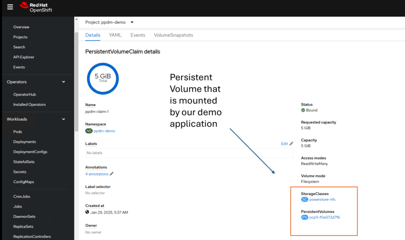


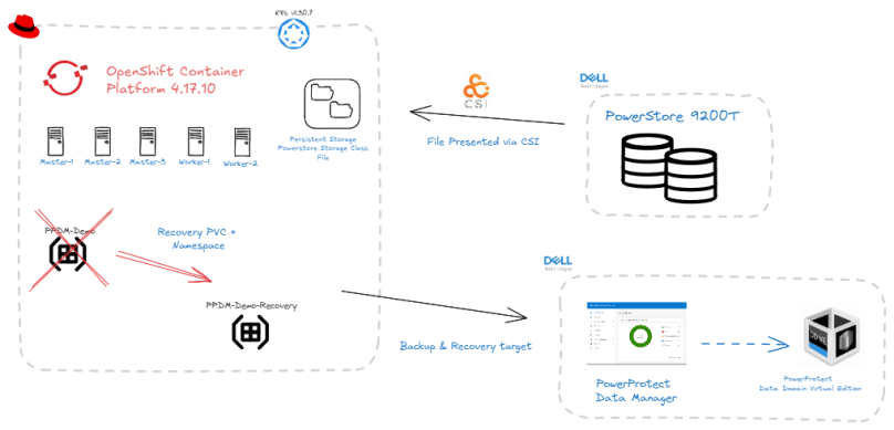


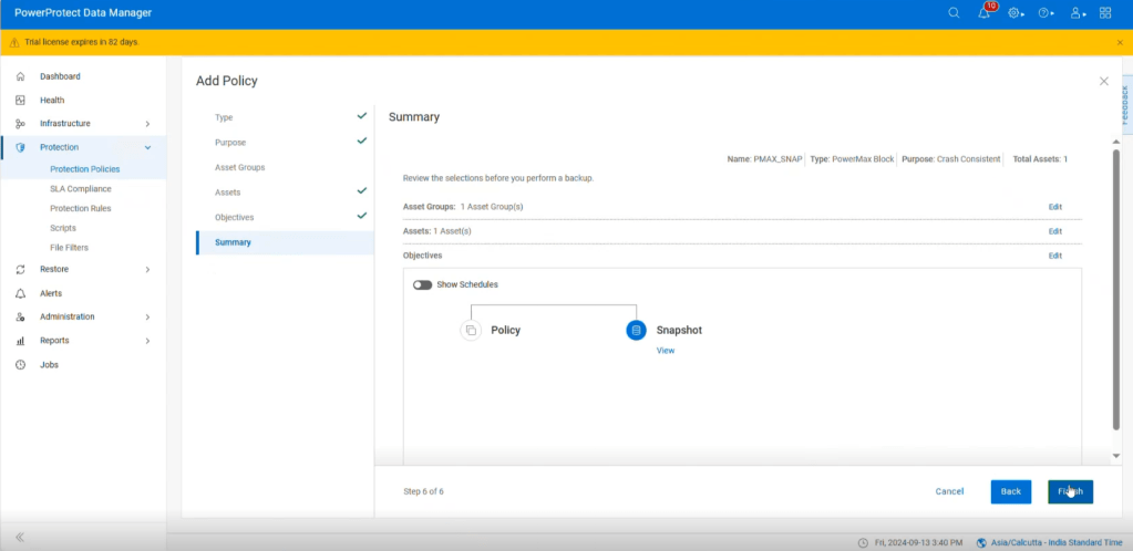


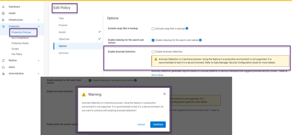
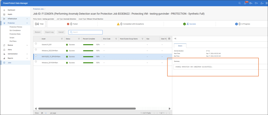
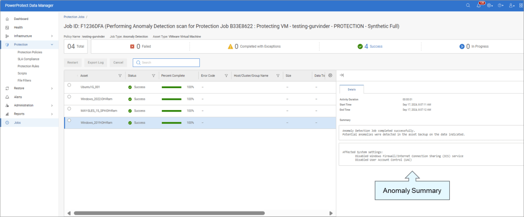


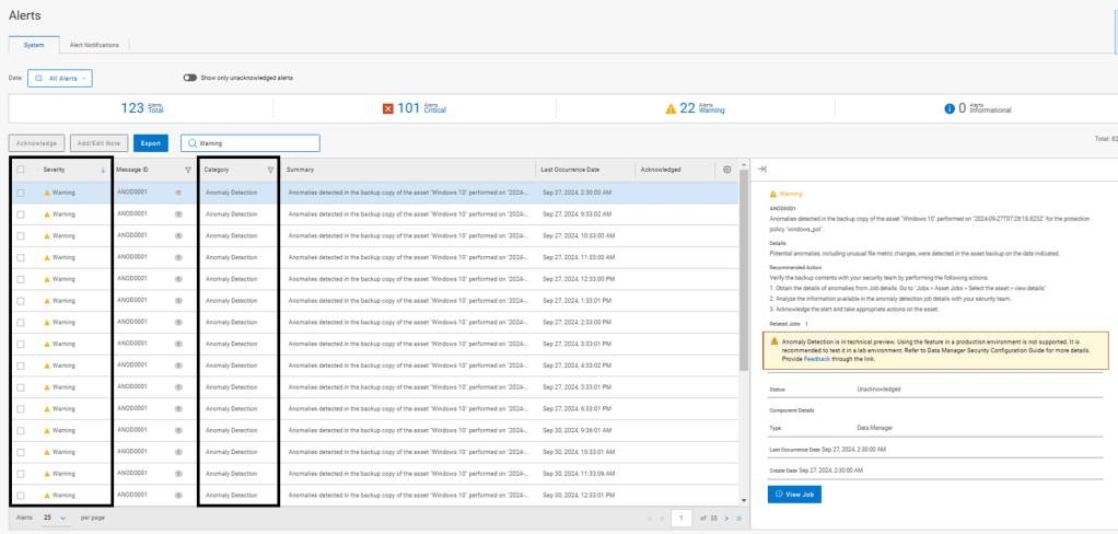


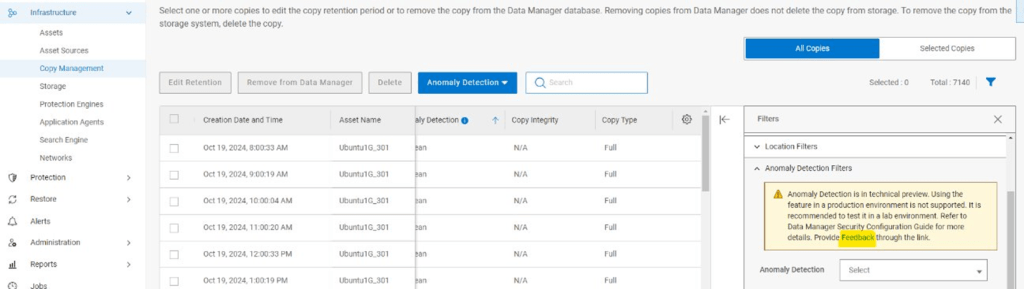
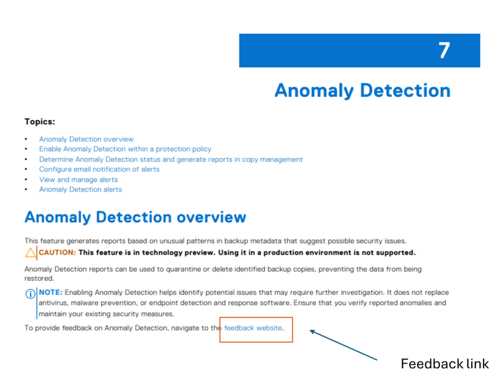

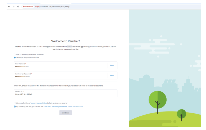

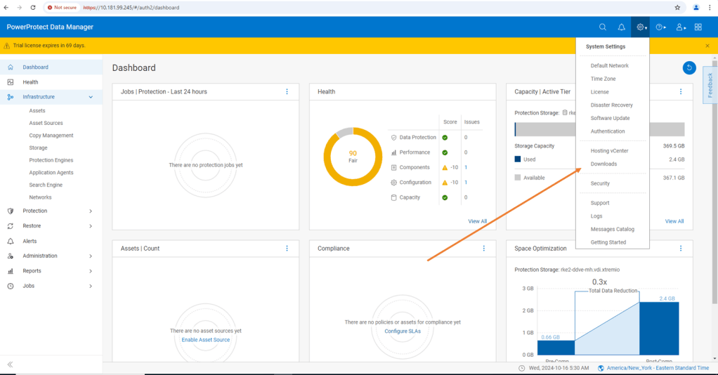

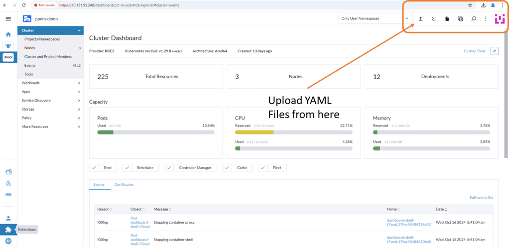
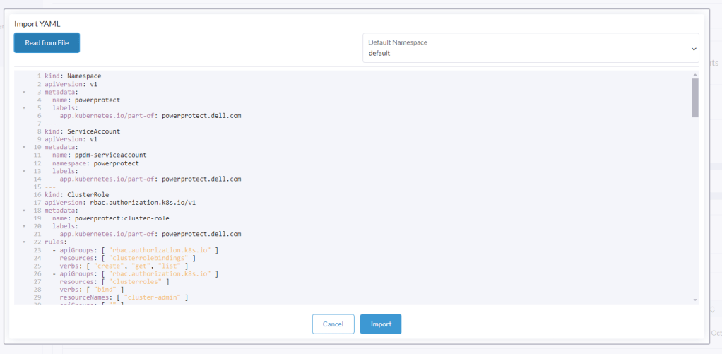


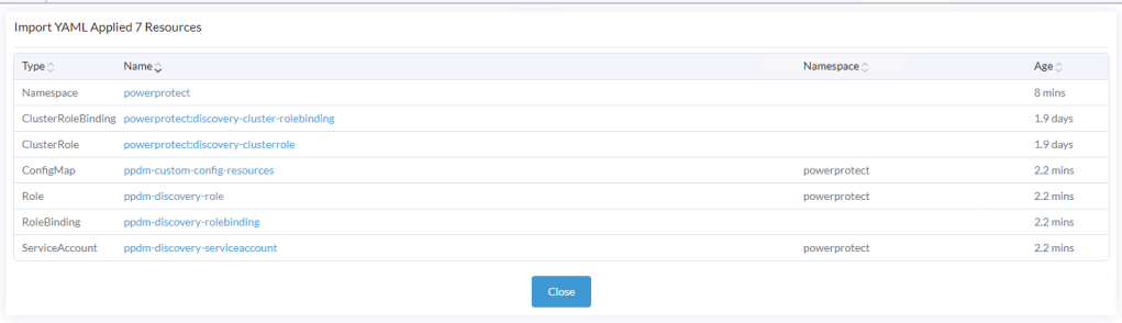

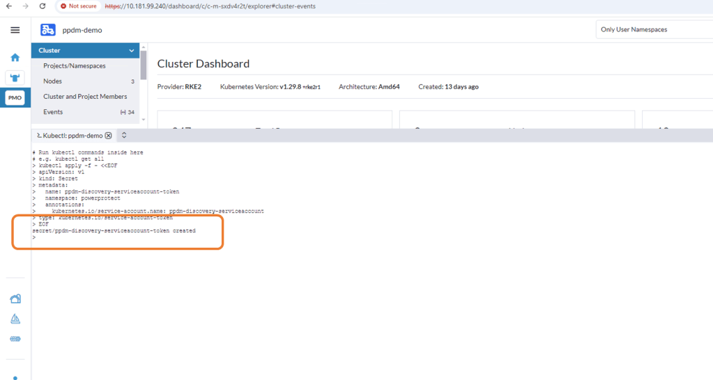
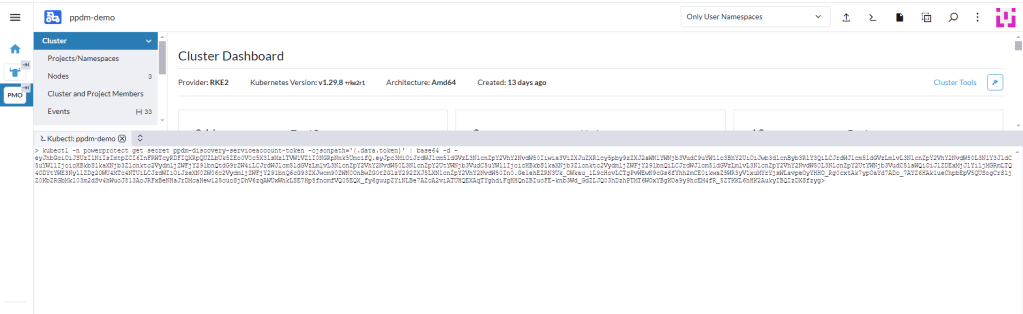


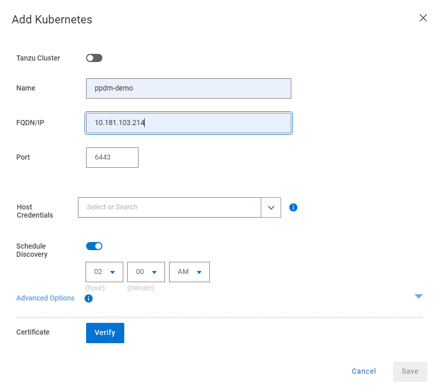

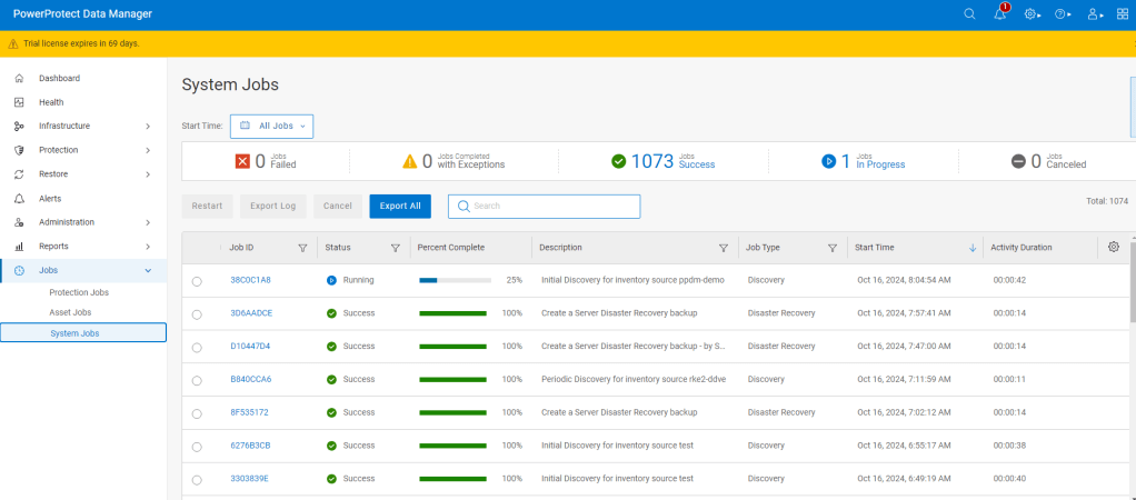
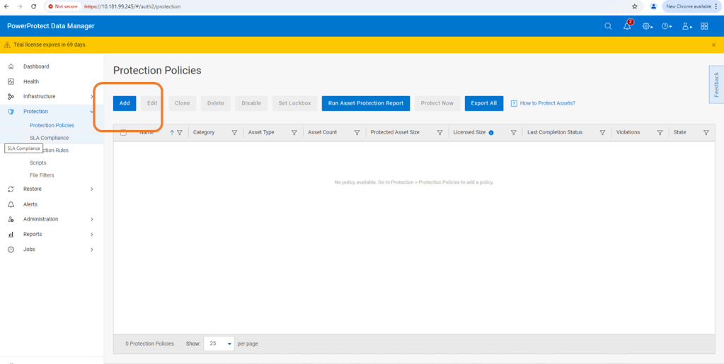
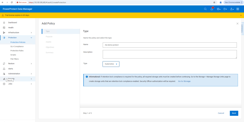
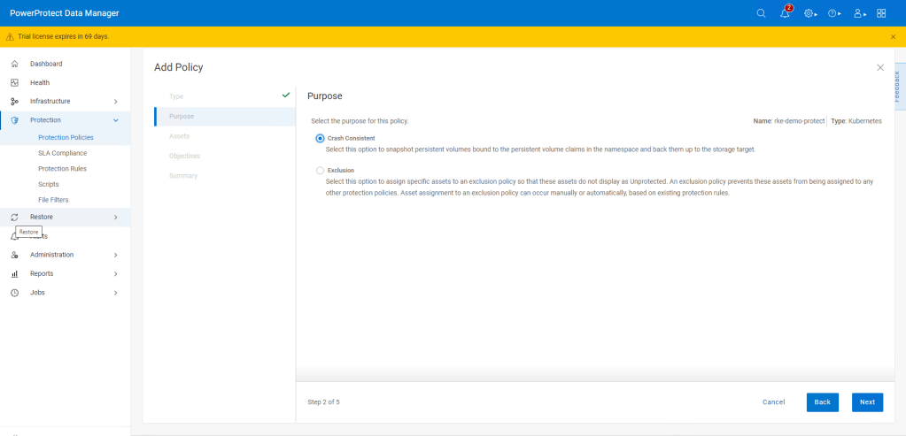

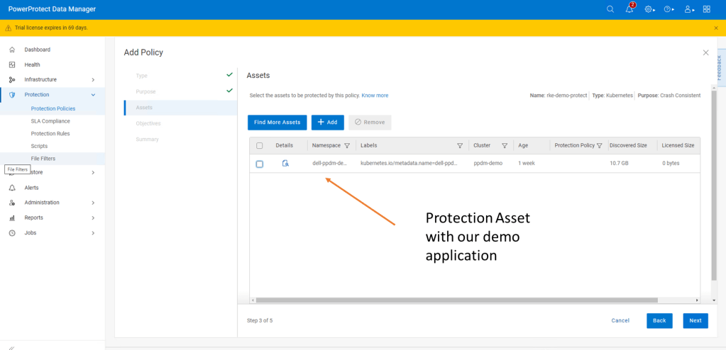


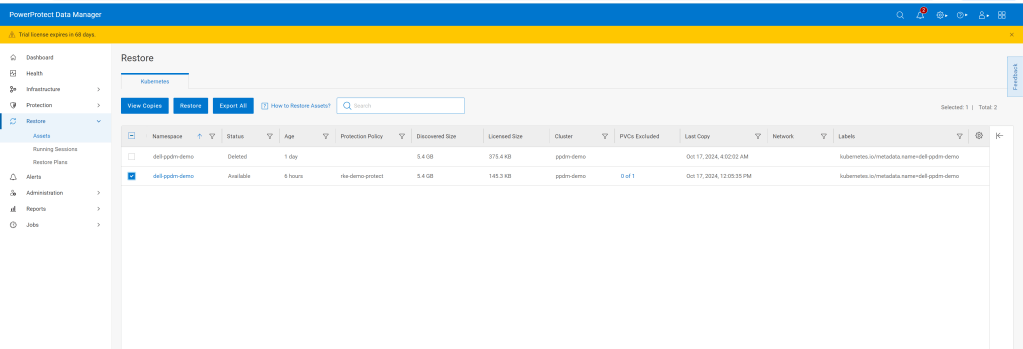
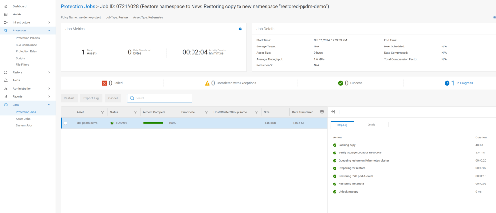
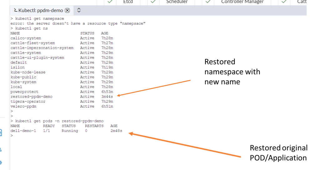
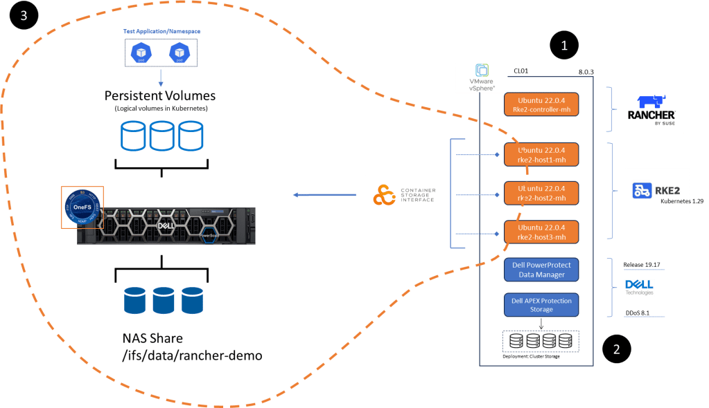

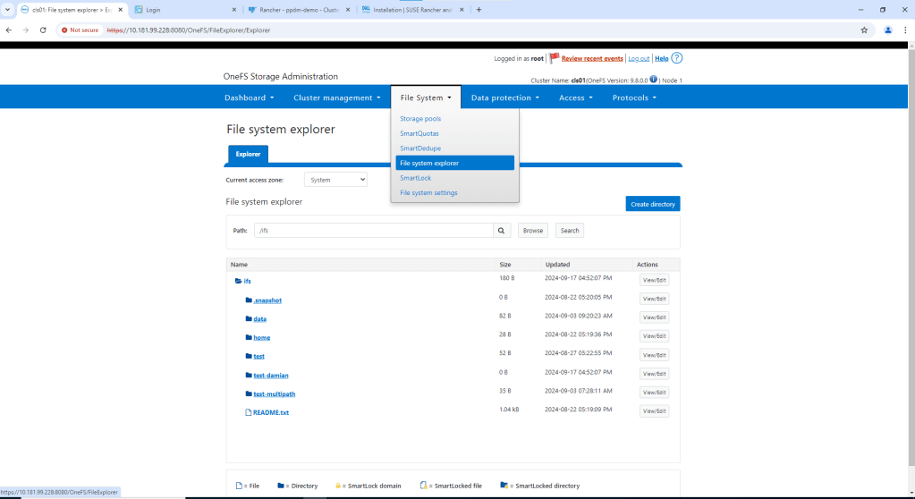


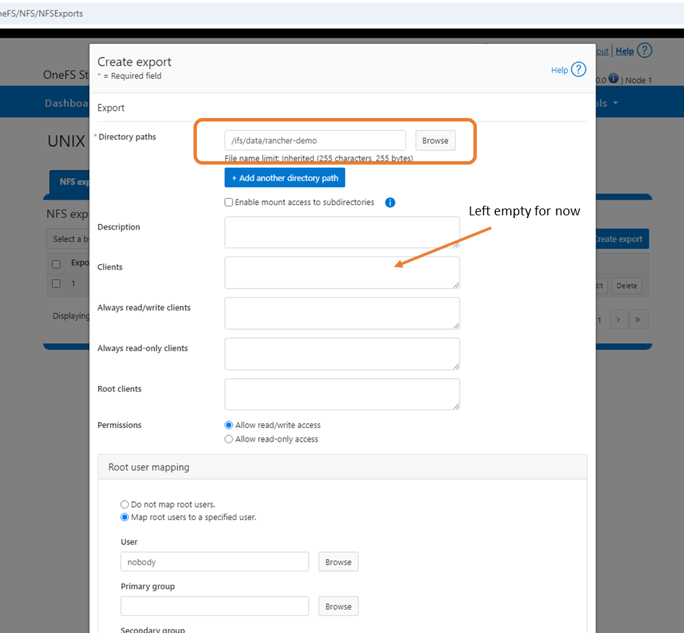
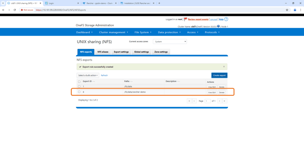
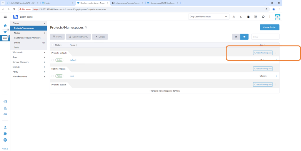

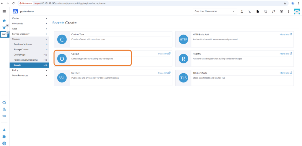
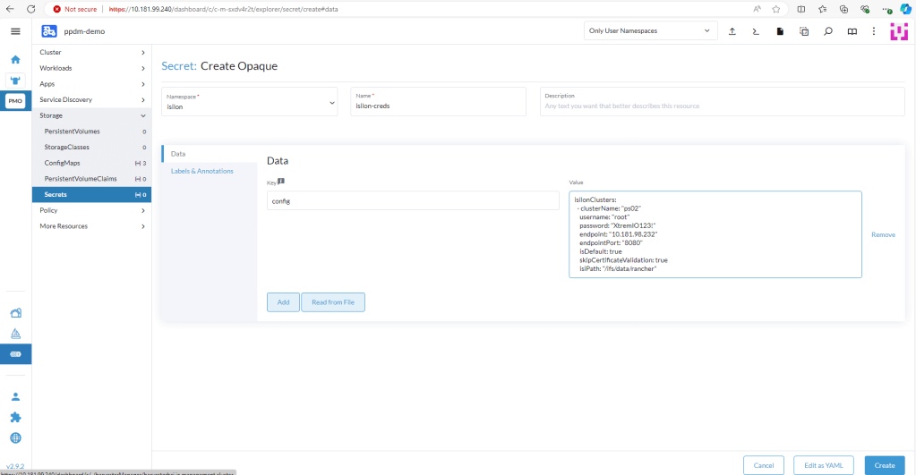
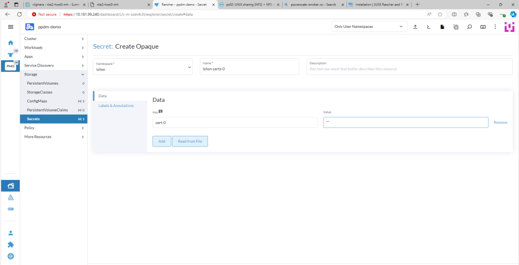
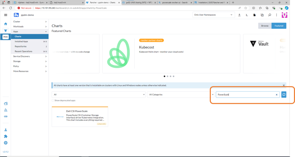
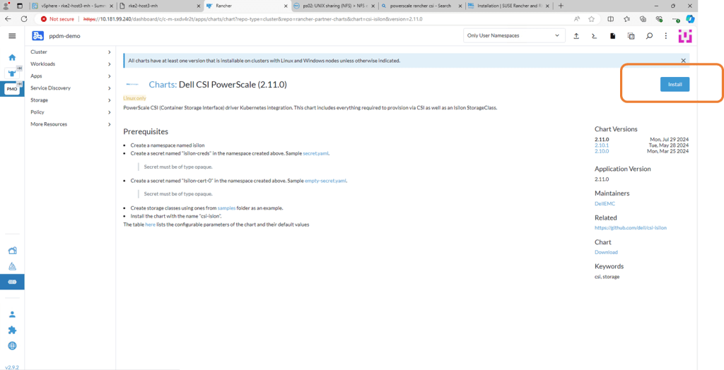
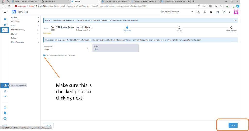

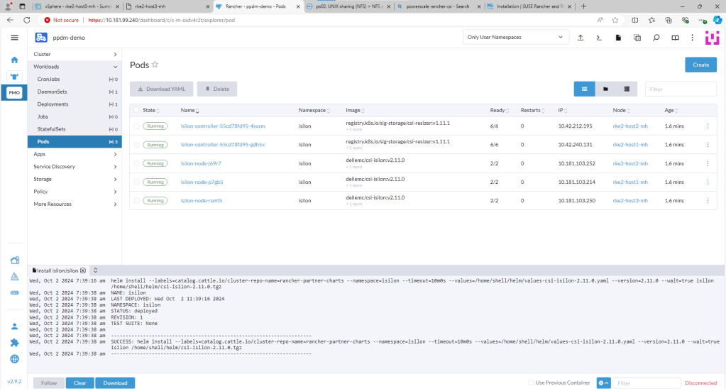

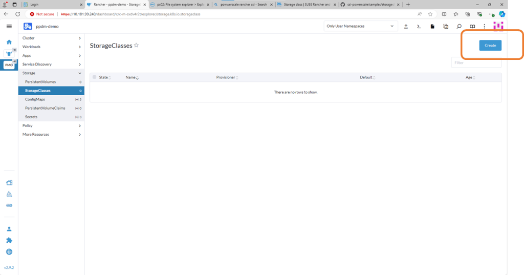

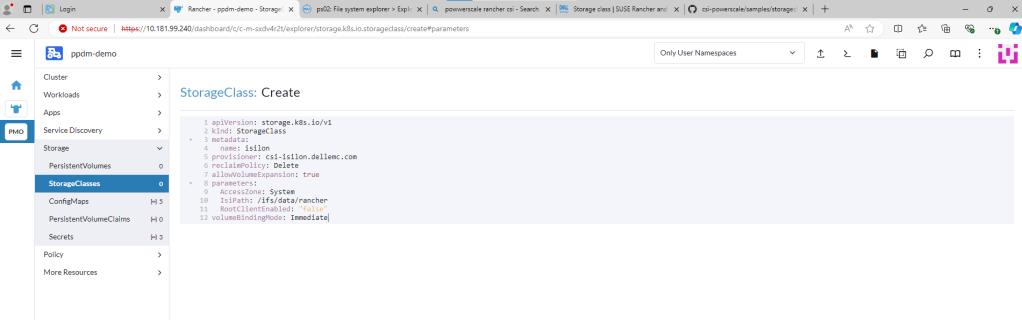


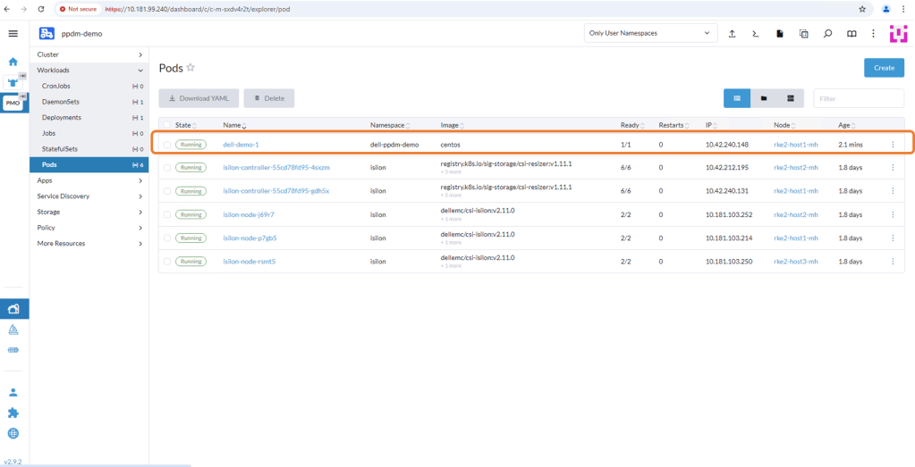
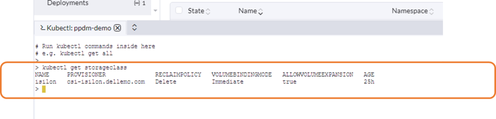
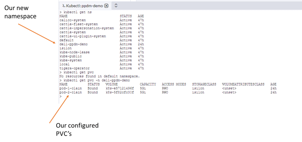


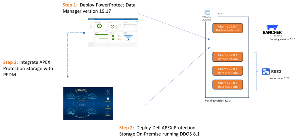

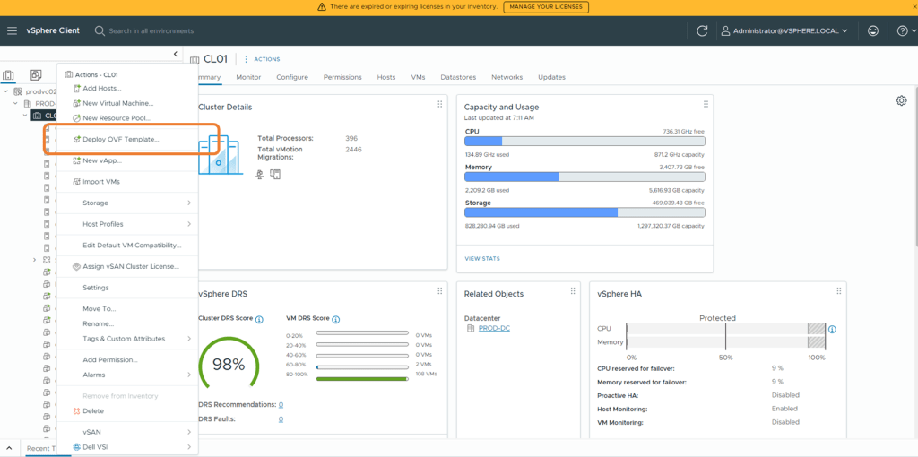

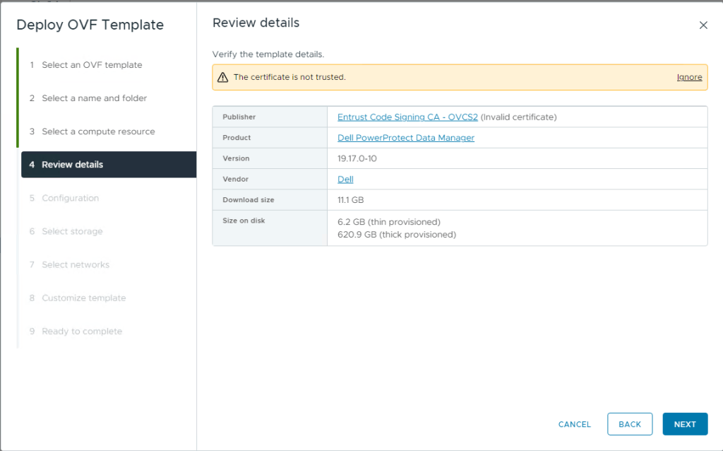


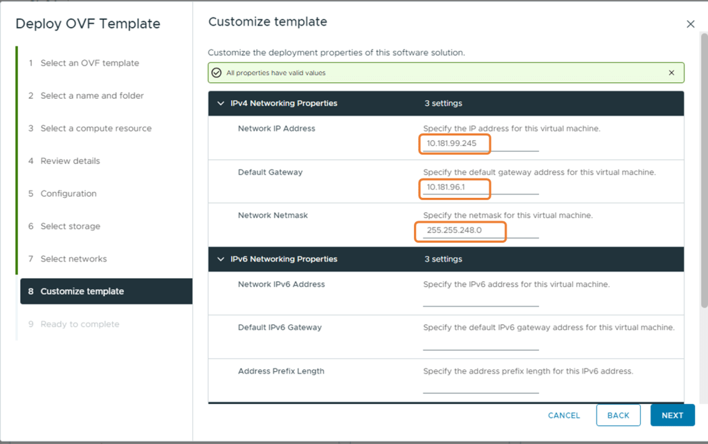


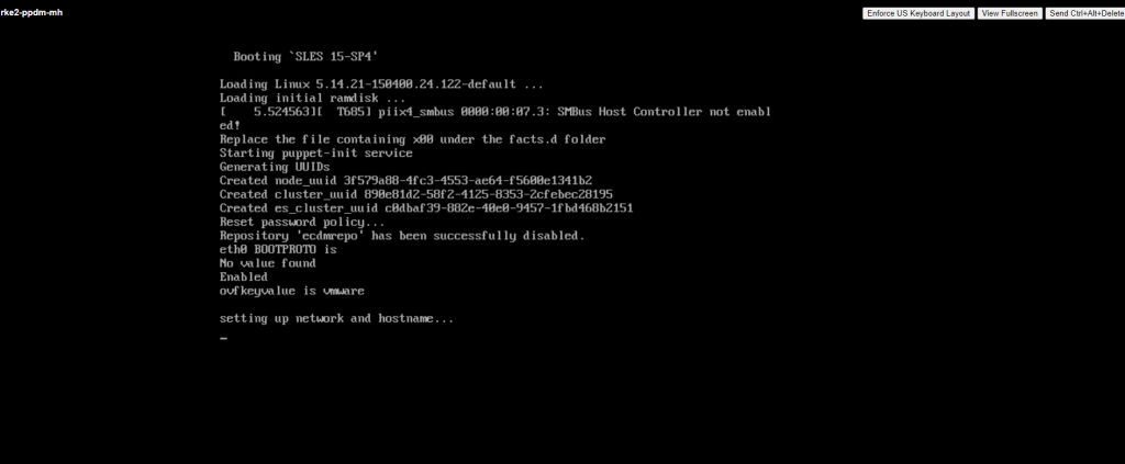
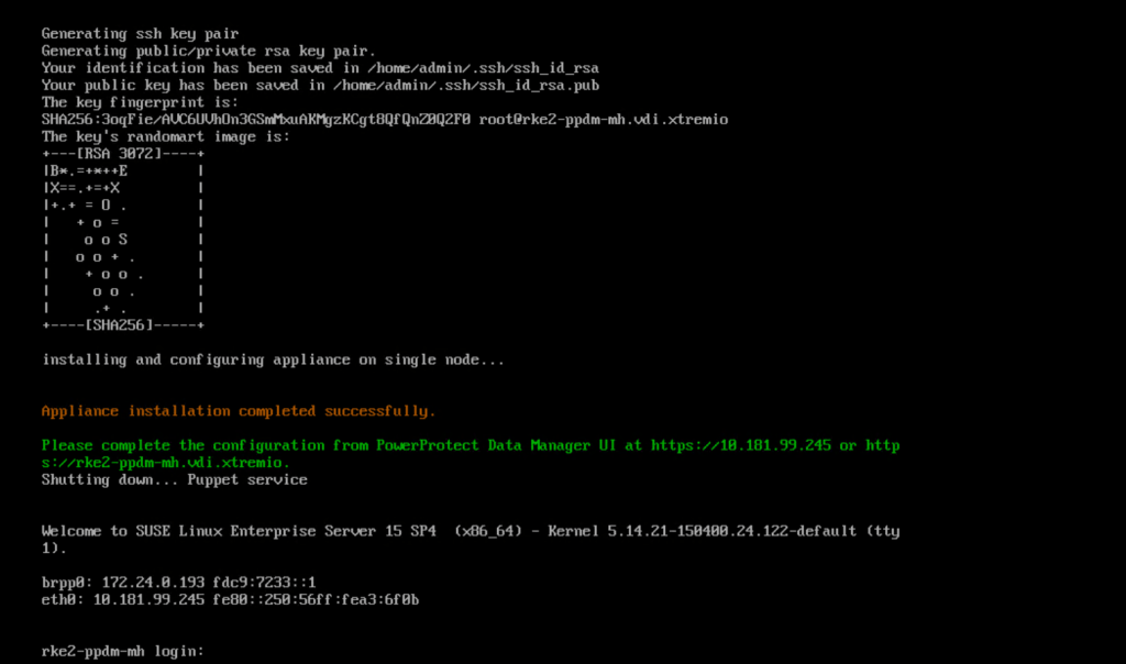
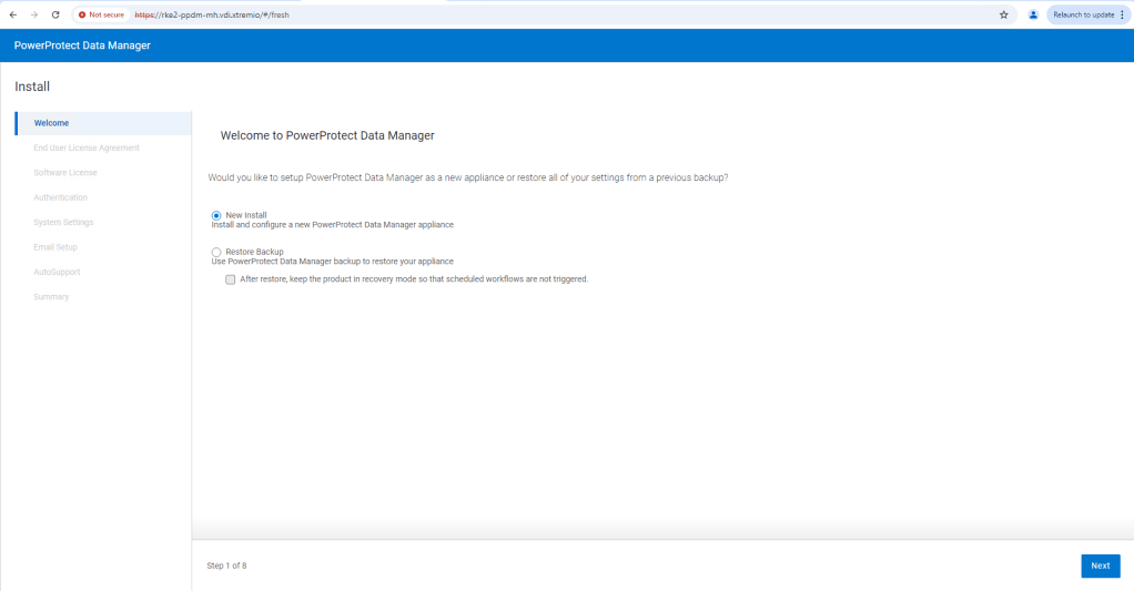
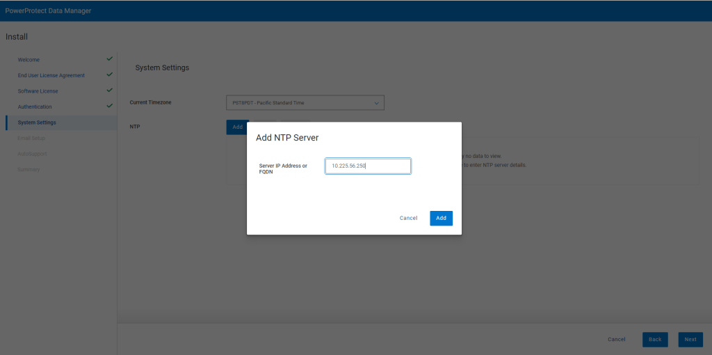

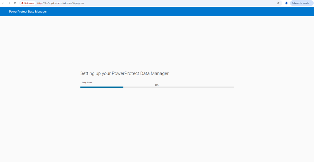


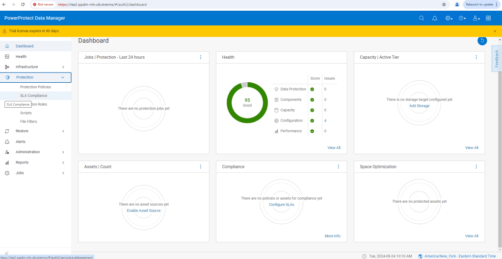
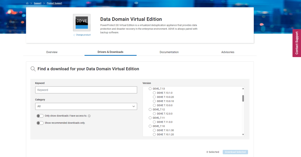

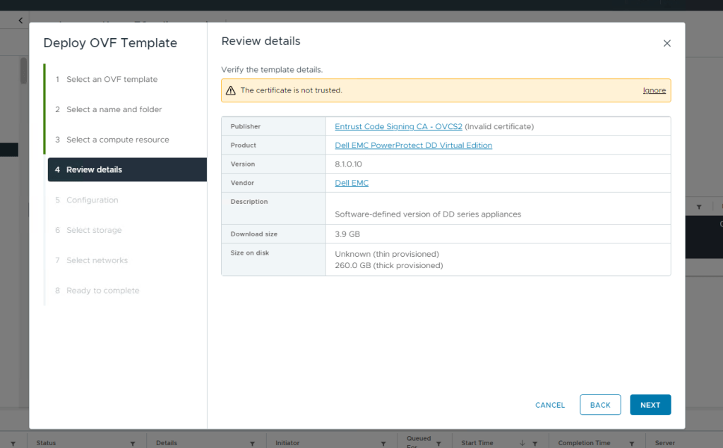


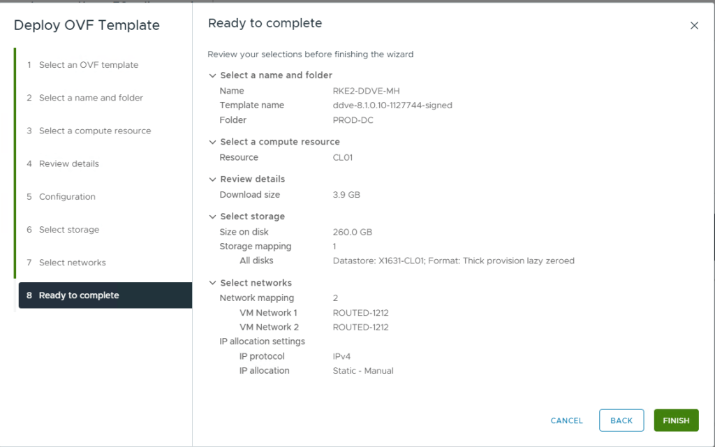

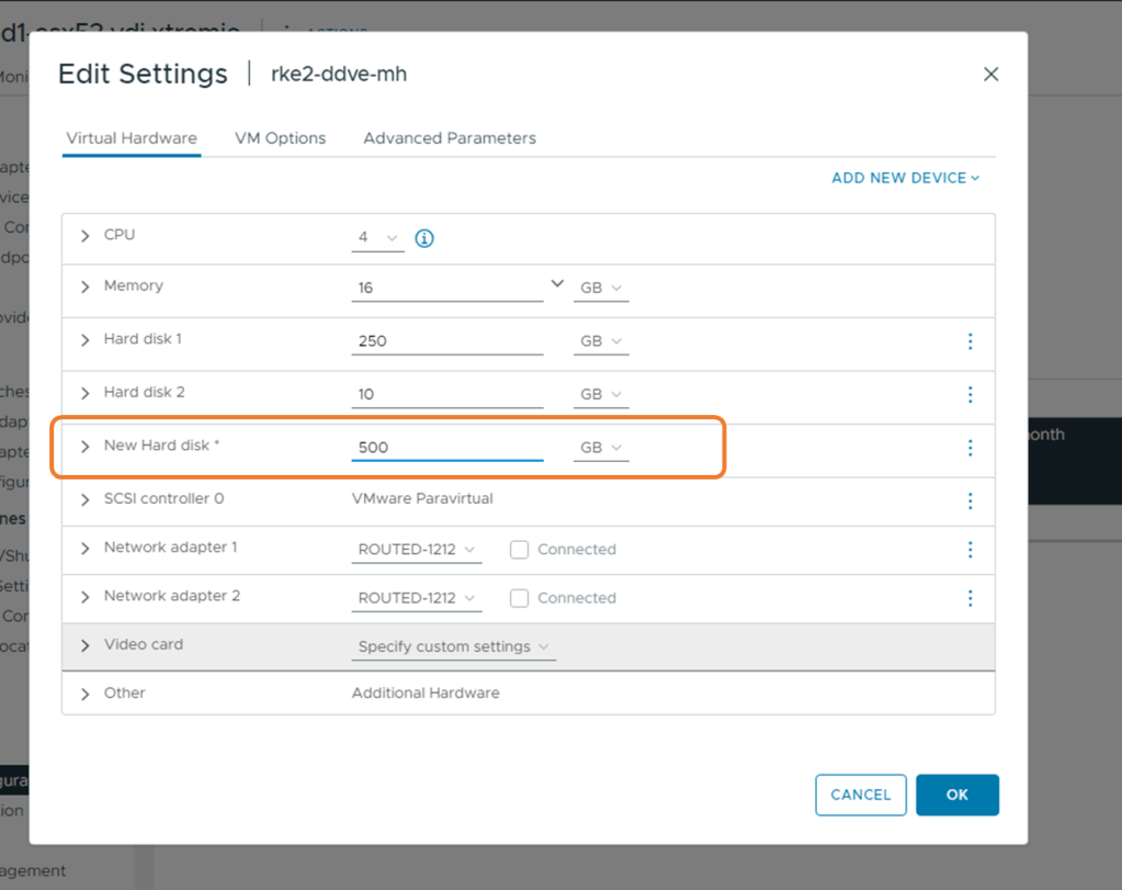


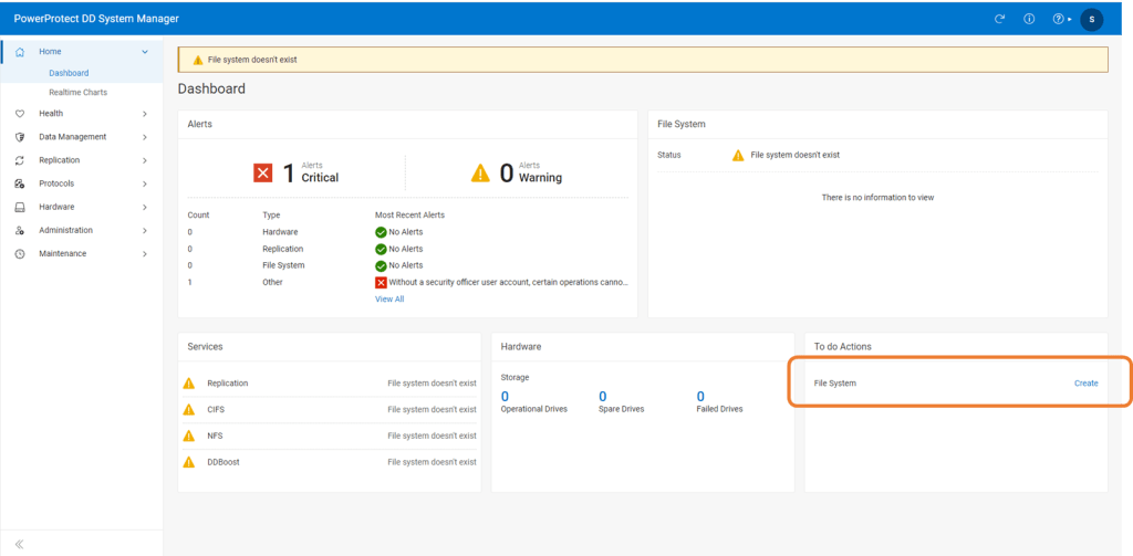

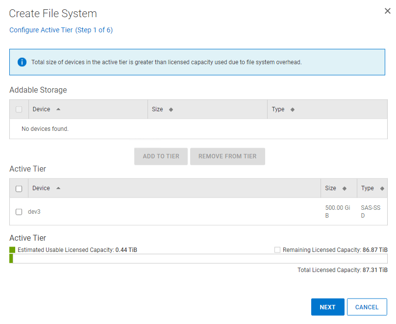

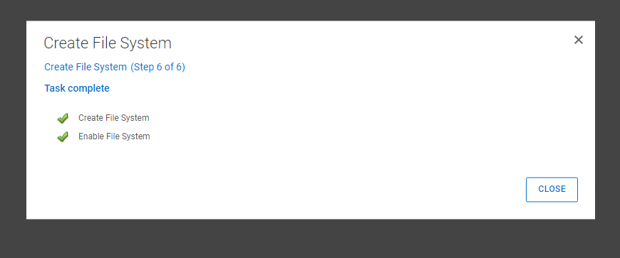


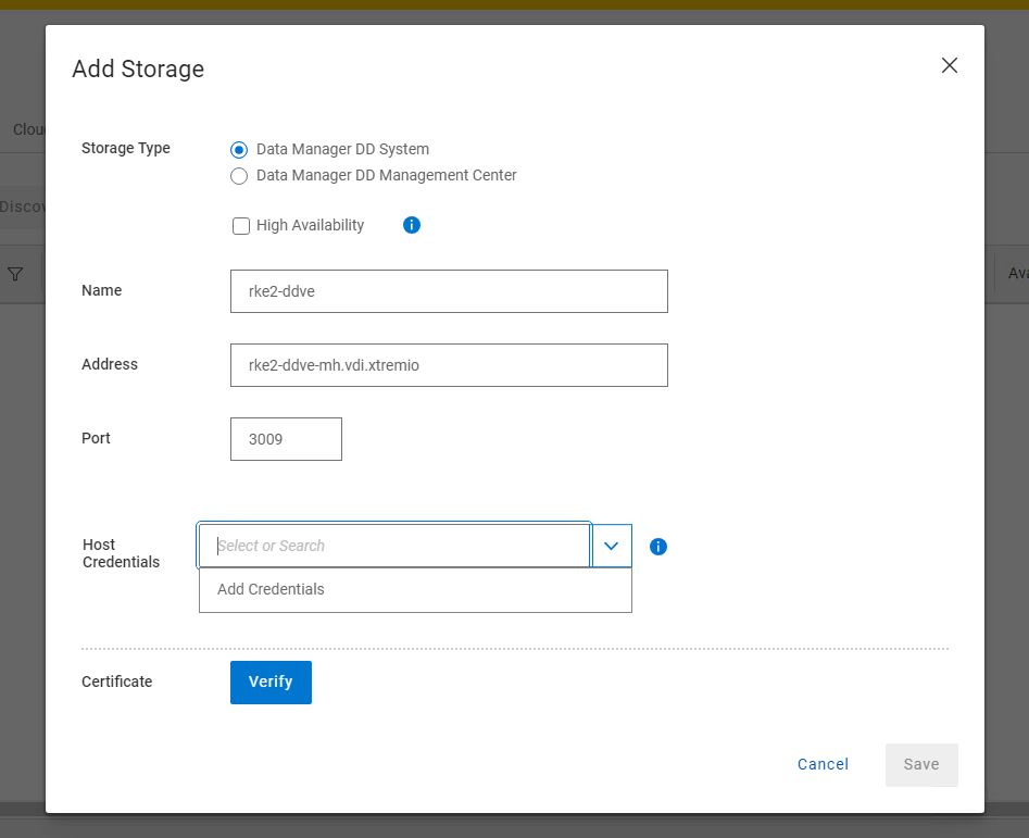

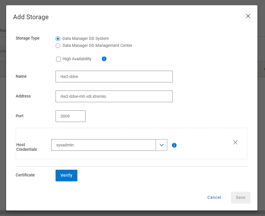


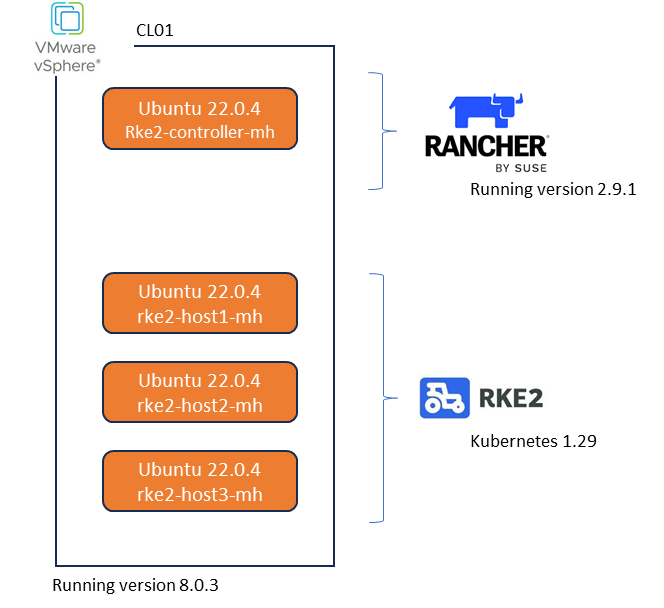


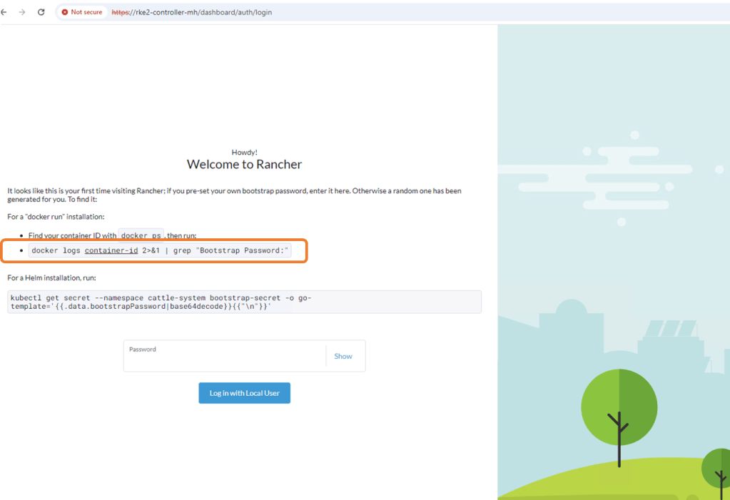


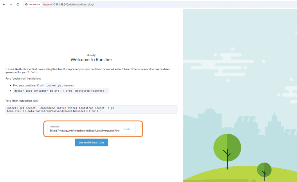

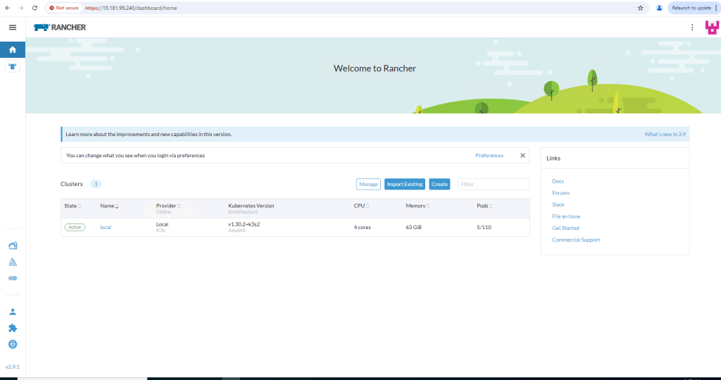


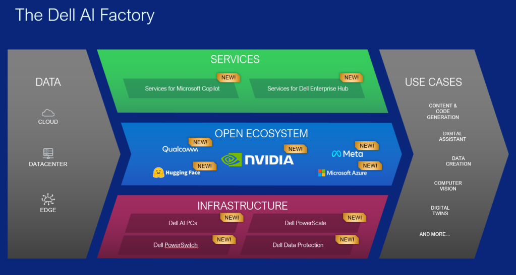
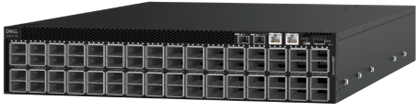

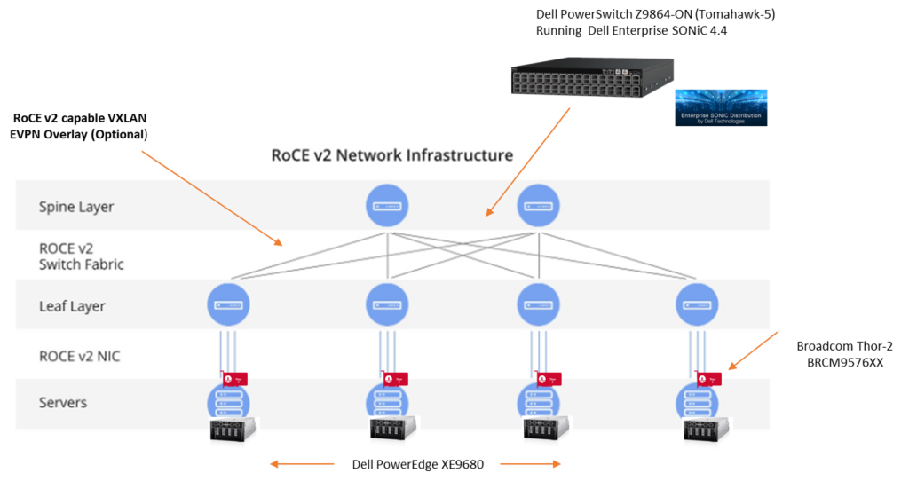
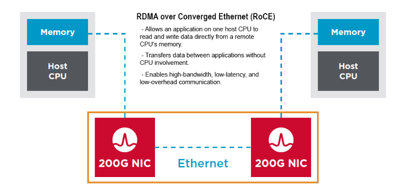
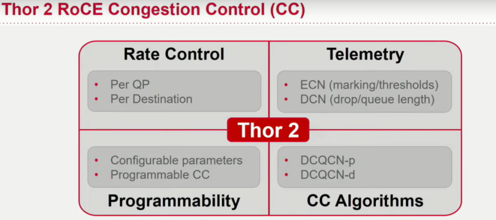

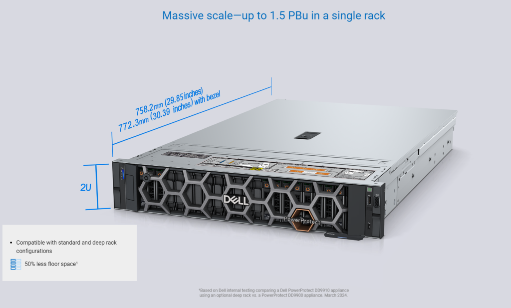
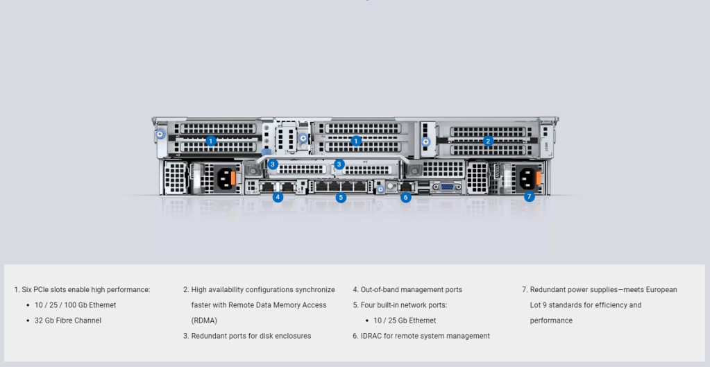
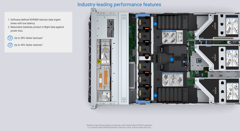
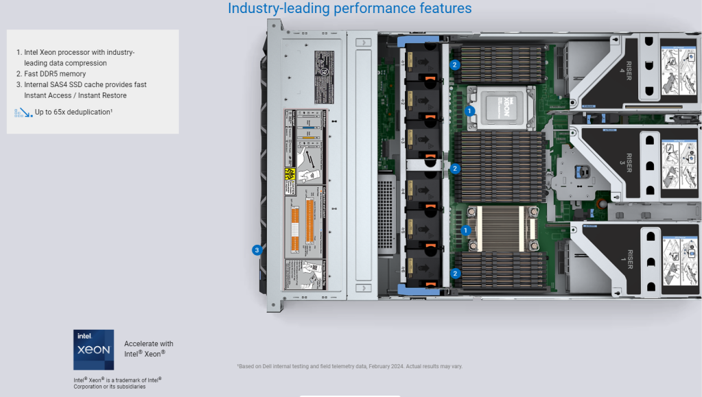

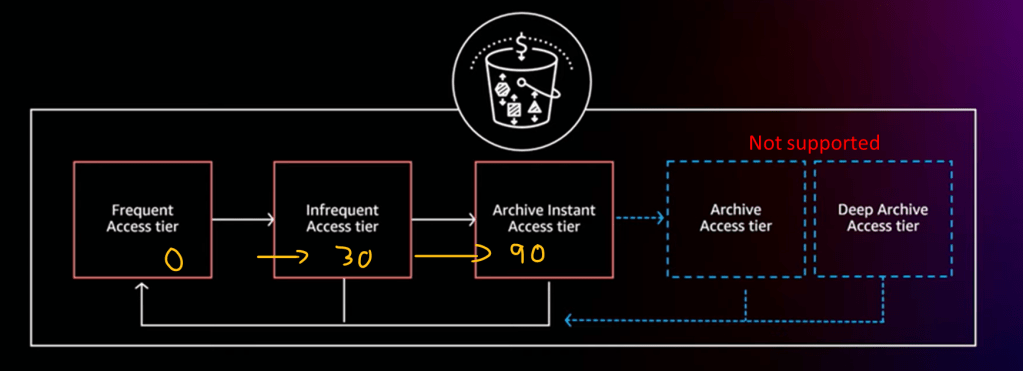


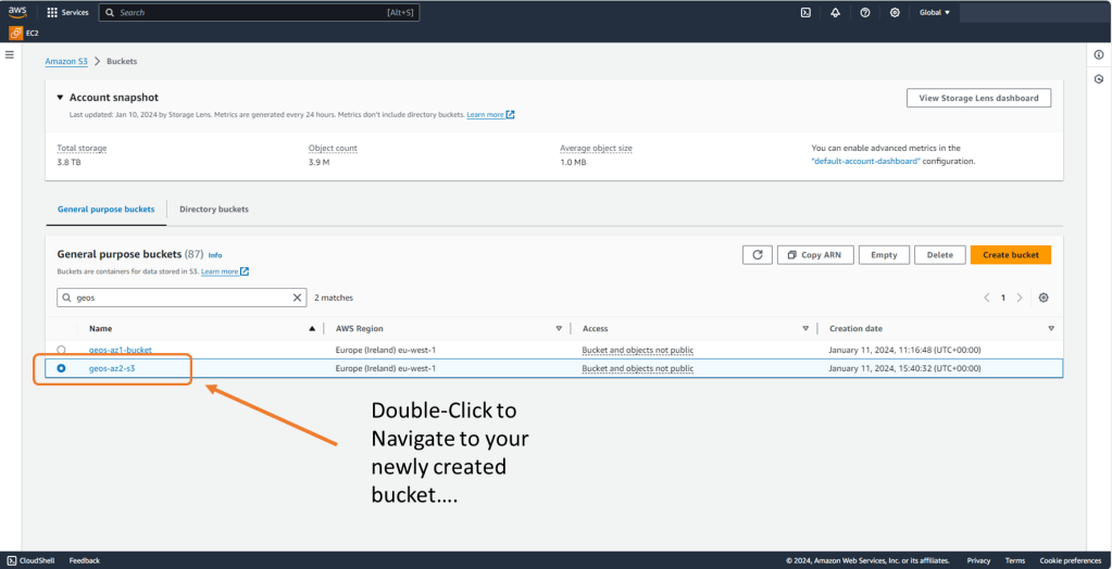
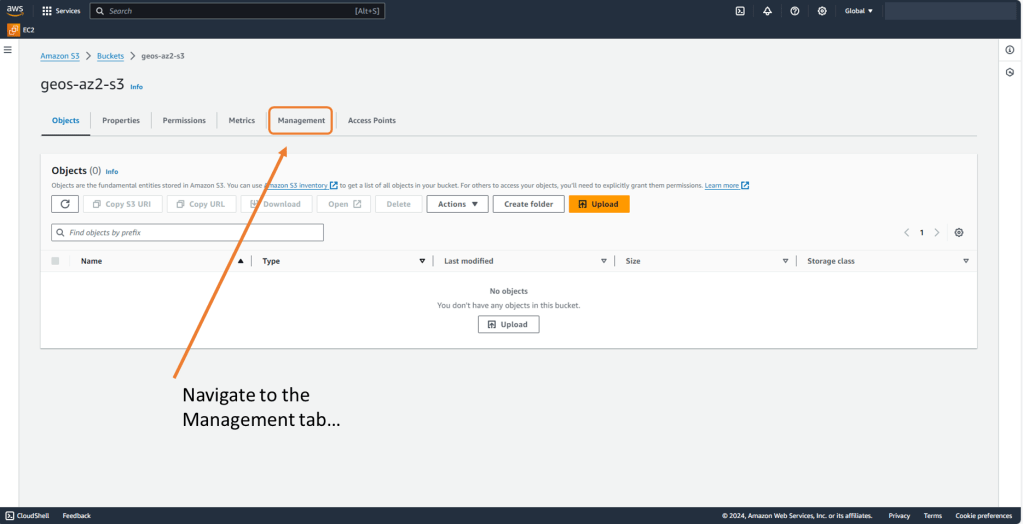


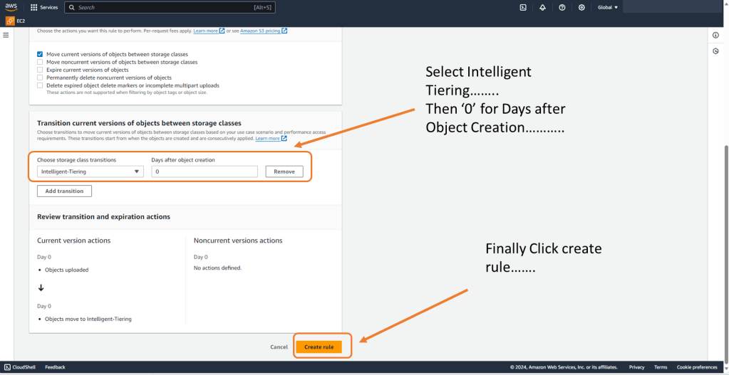
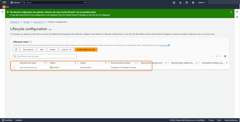


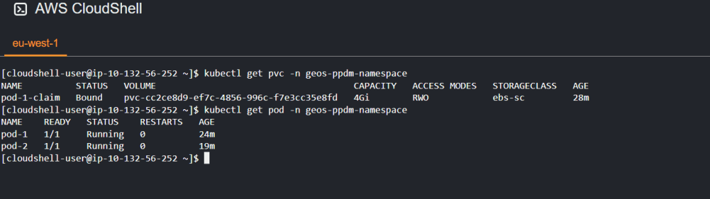


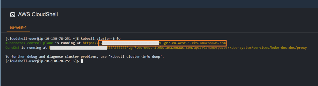


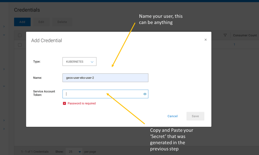


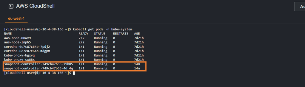

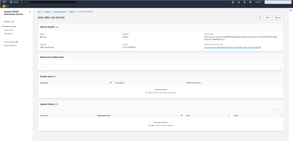


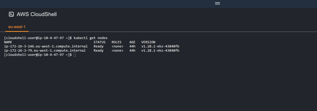


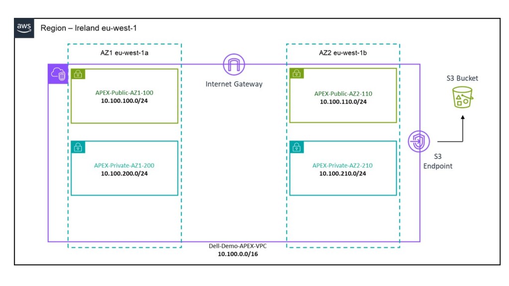
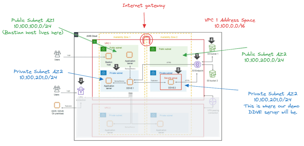
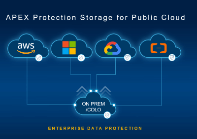


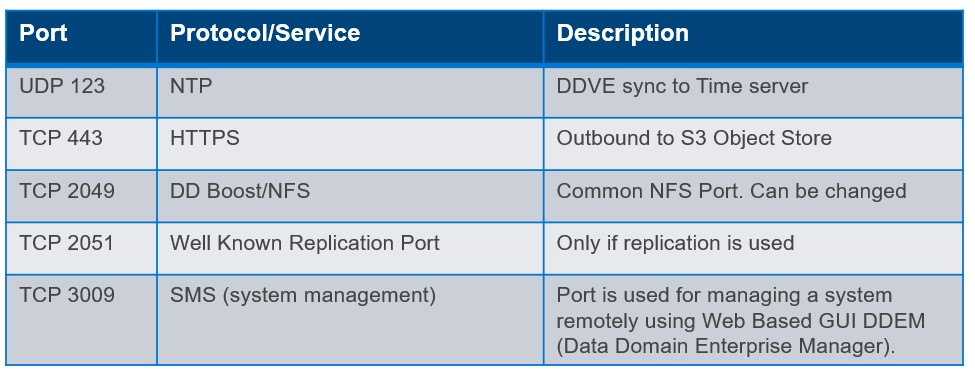
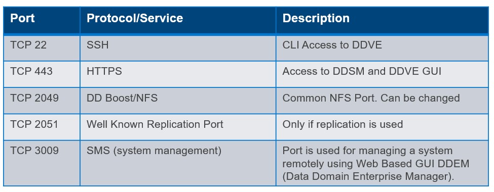


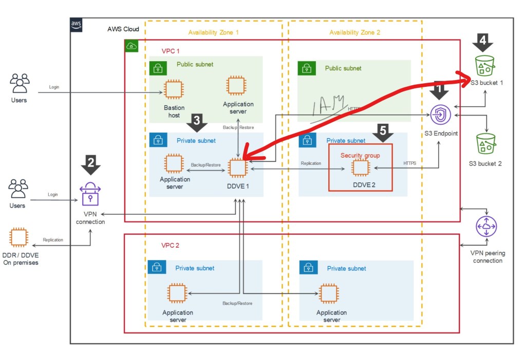
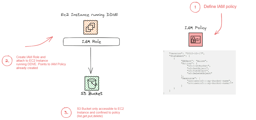


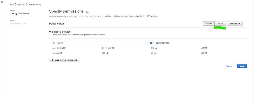

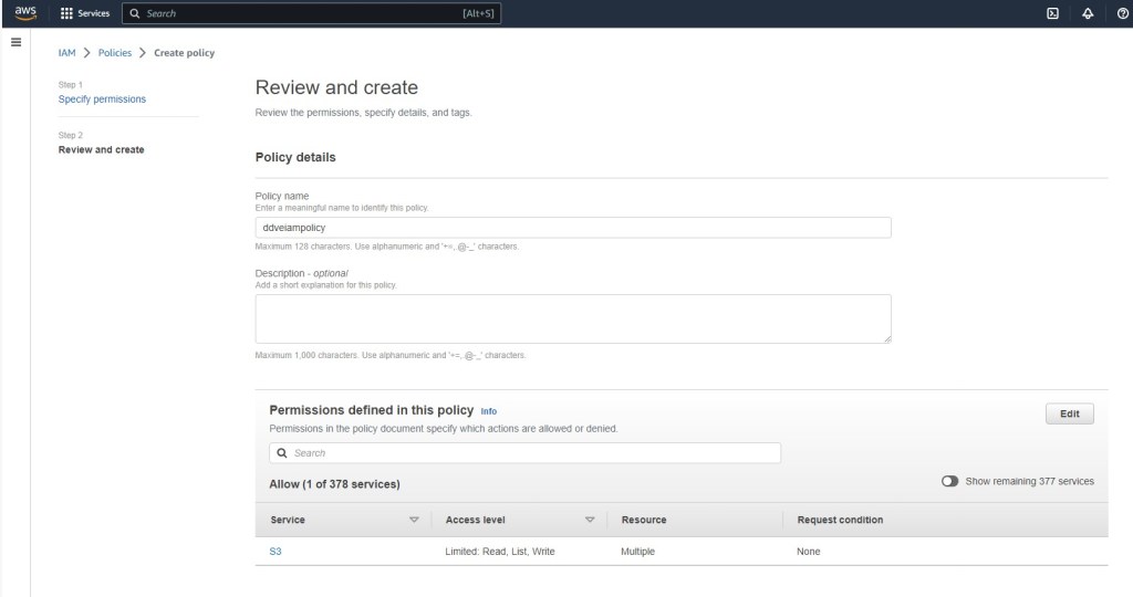

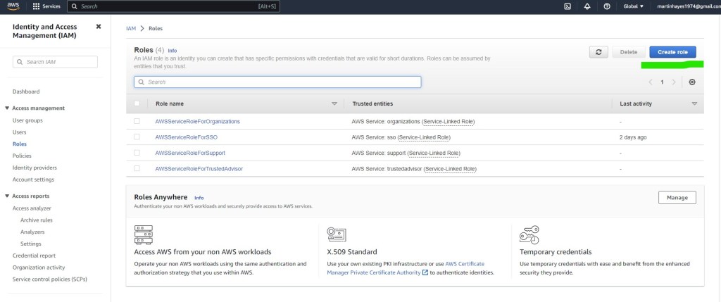


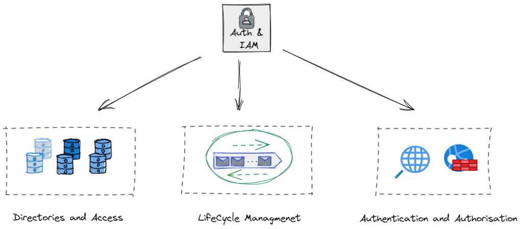
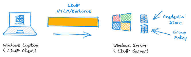


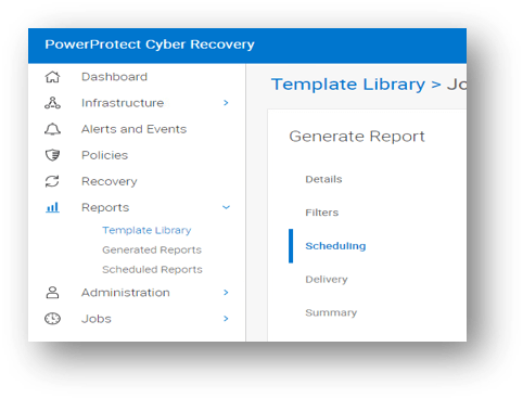
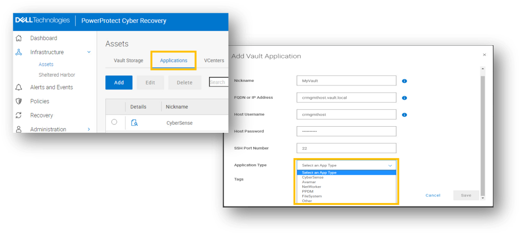
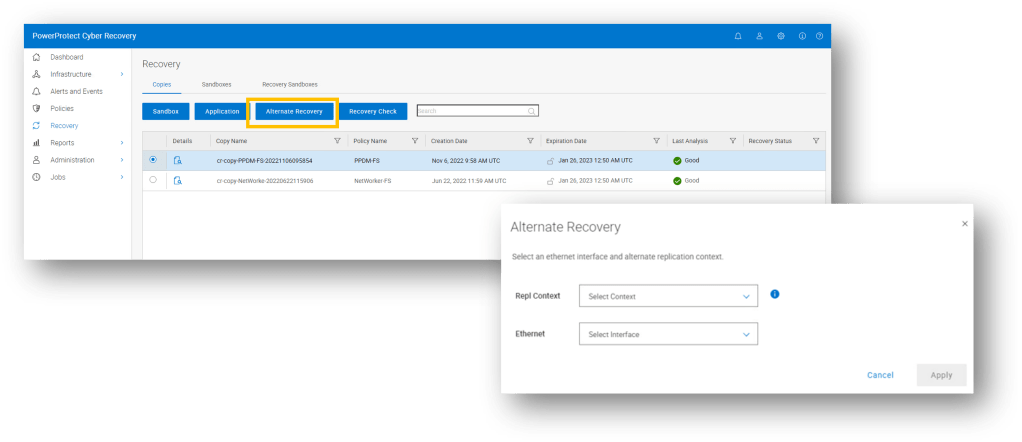


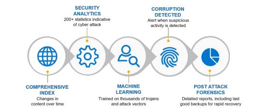


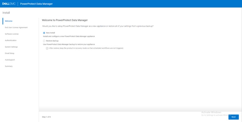

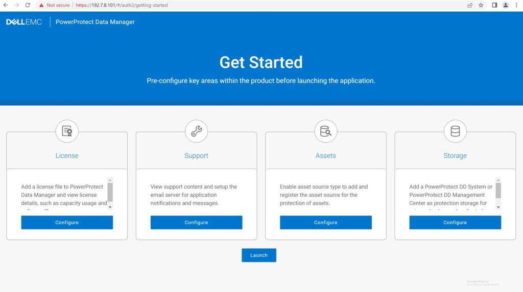

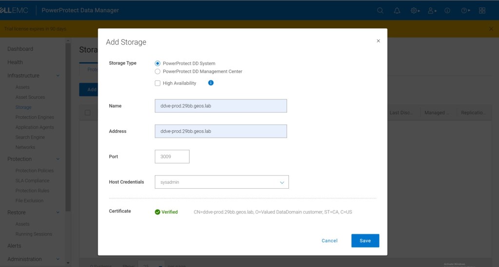


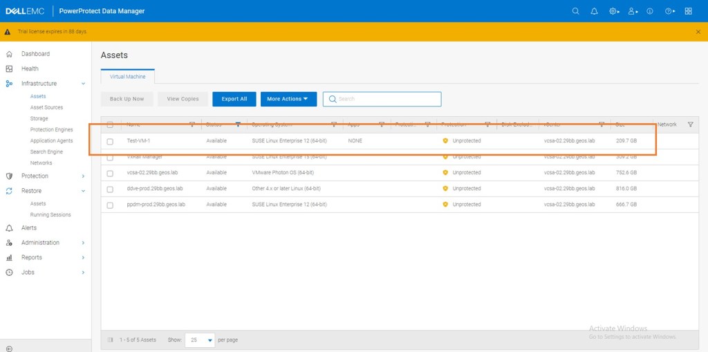


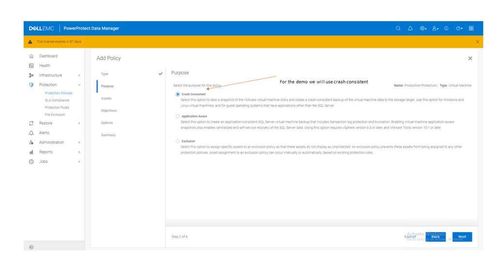


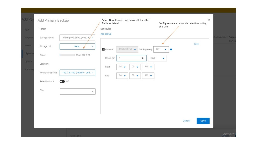

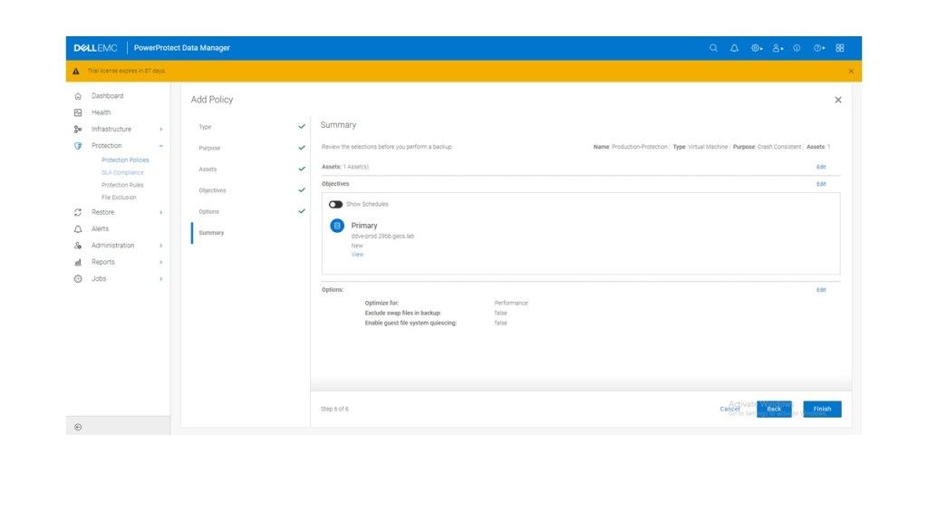
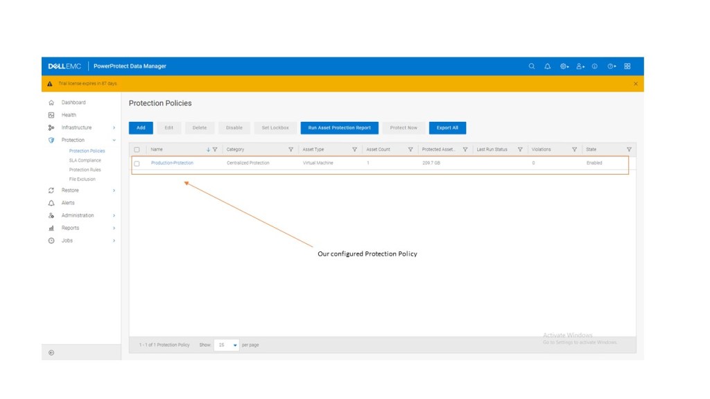
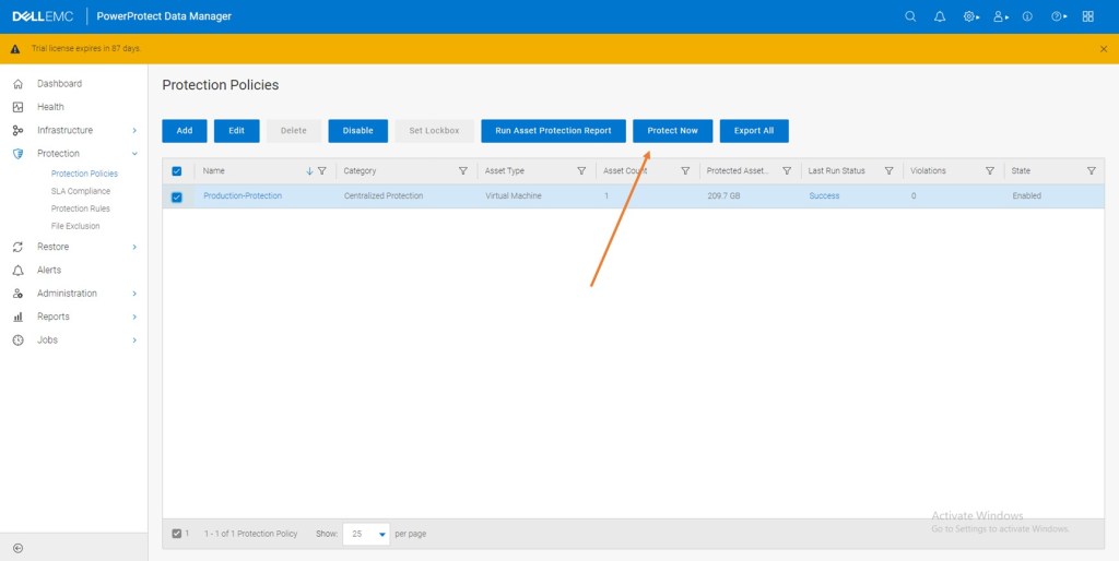

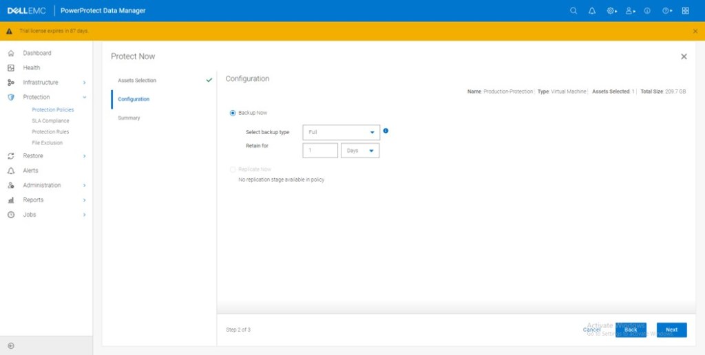


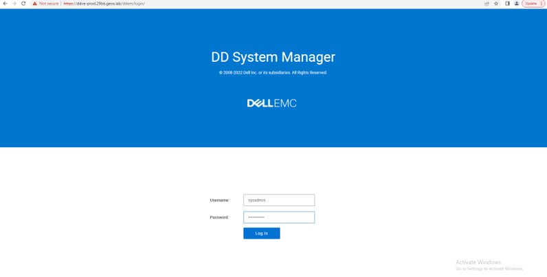
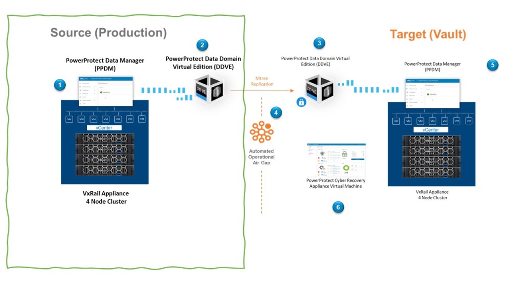
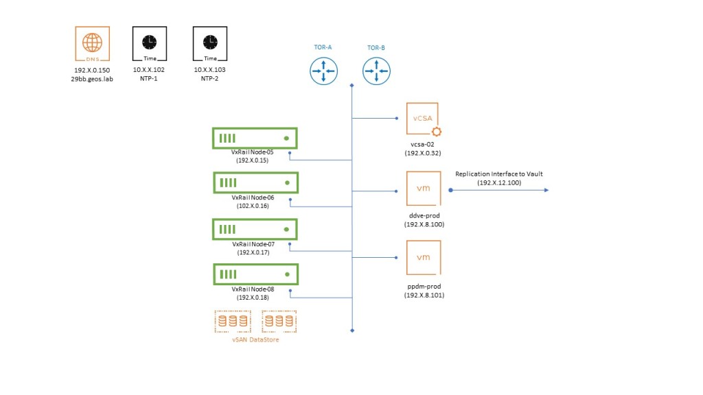


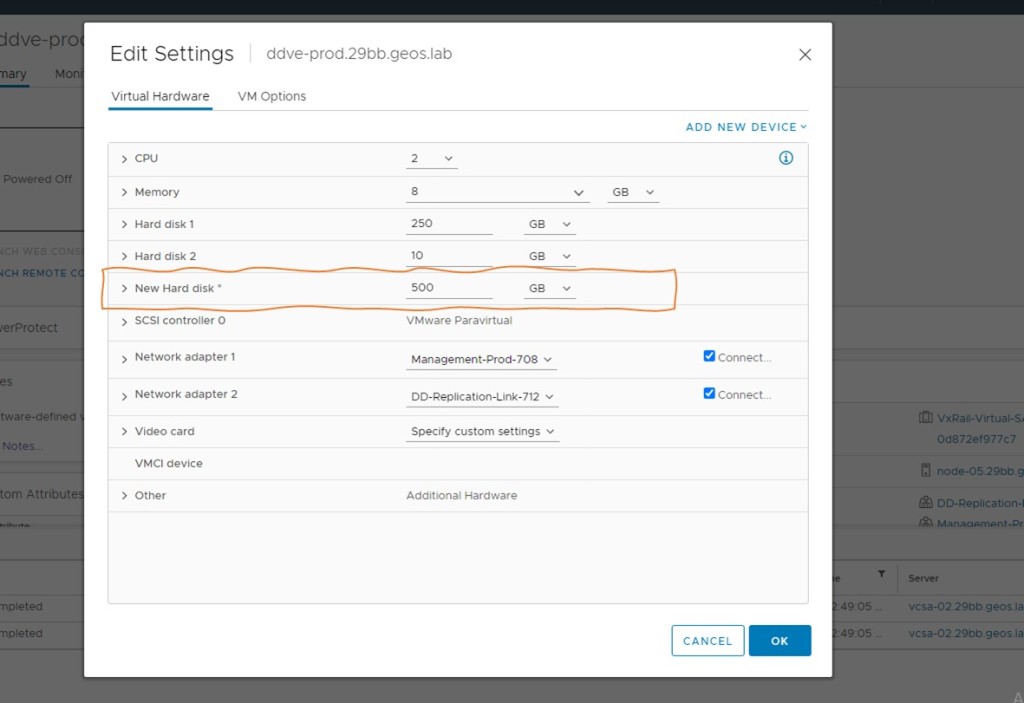
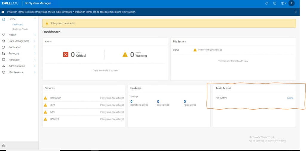
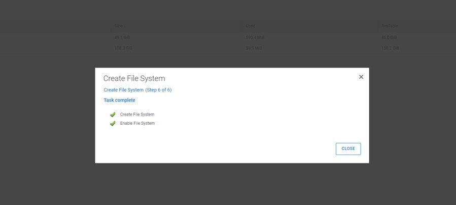
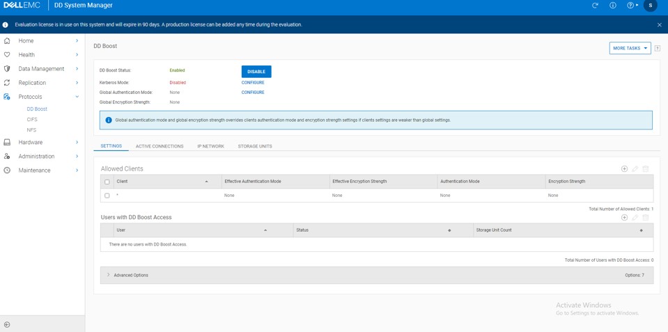
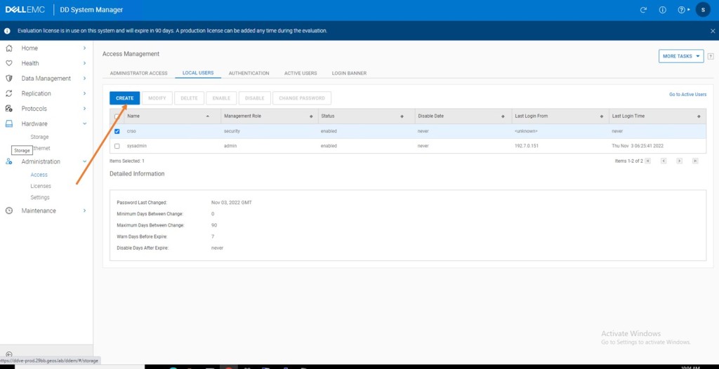
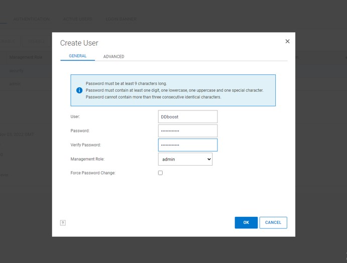

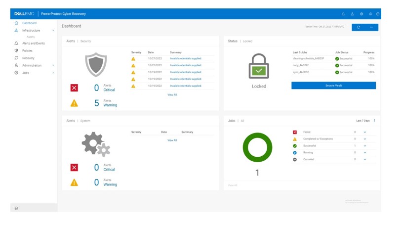
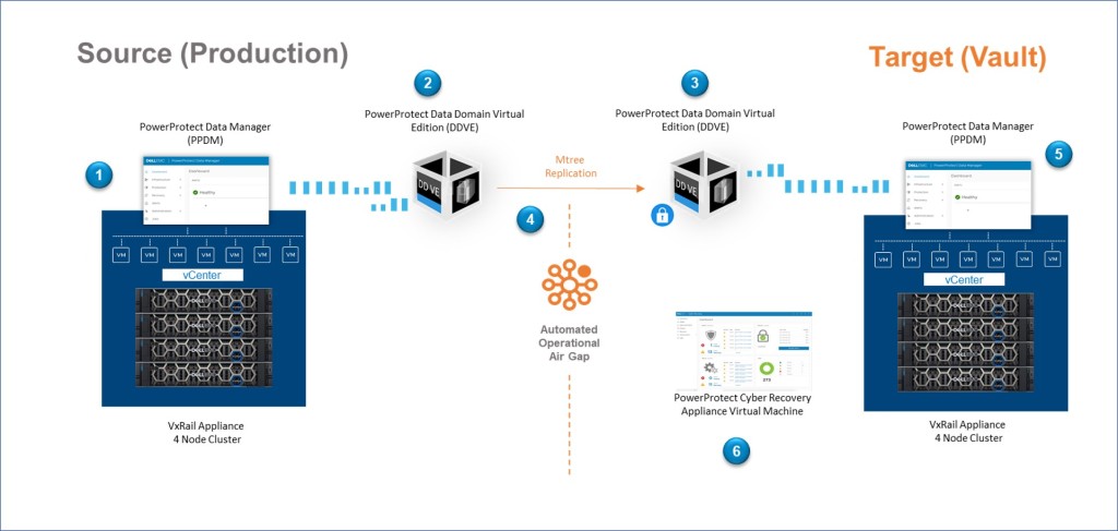


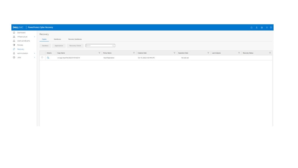


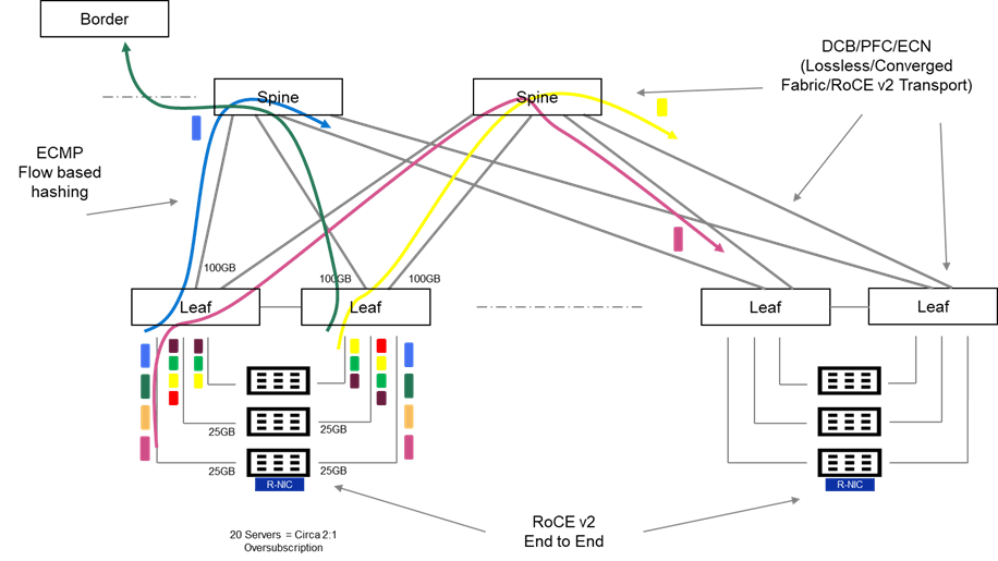
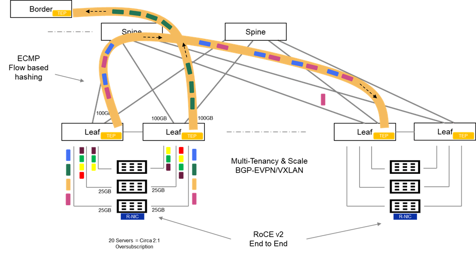


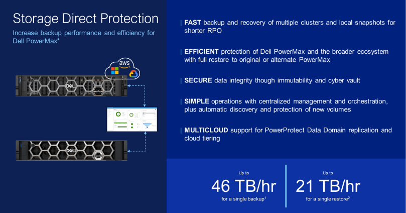


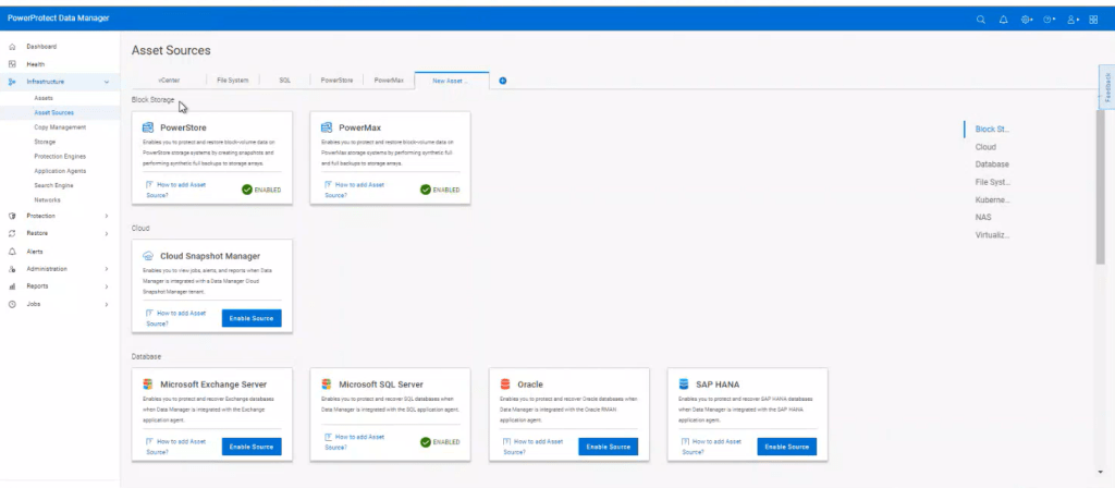
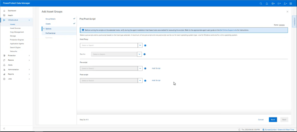

[…] Storage Direct introduced in Release 19.17. I blogged about this feature back in late July. Click here to view…