Recap of where we are at:
Nearly there, we have the following in place:
Production Environment:
- Rancher Managed RKE2 Cluster deployed. Link to blog post here.
- Dell CSI for PowerScale configured to present persistent storage to our environment.
- An application running in our environment in a new production namespace writing data to a PowerScale NFS target. Link to CSI configuration and demo application blog post here.
Protection Environment:
- Dell PowerProtect Data Manager deployed and running. Link to post here.
- Backed by Dell PowerProtect Data Domain (APEX Protection Storage)
The next step is to demonstrate how we knit our ‘Production Environment’ and our ‘Protection Environment’ together.

Use of External Load Balancer:
If this was a production environment, where we have distributed the K8s control plane across all 3 active nodes, then we would deploy an external TCP/HTTP Load Balancer such as HAProxy in front of the control plane to distribute API activity into the cluster and provide HA for the API access process. Clearly this is a really important topic and we will dig into it in more detail in an upcoming blog post ( when we do this in production we don’t want stuff to break!). For now though, to keep things simple lets park that conversation and point PPDM directly at one of the active control plane nodes in the cluster.
Step 1: Discovering RKE2 Kubernetes Cluster
Natively within our Kubernetes cluster within the kube-system namespace, the necessary user permissions exist to execute the discovery and to allow PPDM to configure the RKE2 cluster via the API. (We will see later that PPDM configures a new namespace and deploys the Velero application etc). Personally, I have a preference to segregate this activity to a new user bound with net new permissions. Luckily this is a straightforward process and you can download and deploy the necessary YAML configuration files direct from PPDM and execute on your cluster. This is the approach we will take here.
1.1 Download YAML Files to your Management machine
Log into PPDM and navigate to ‘Downloads’ under the gear icon at the top right of the GUI
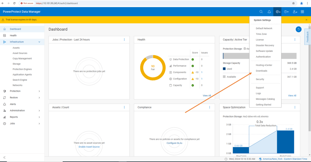
From there, open the Kubernetes tab on the left hand side and download the RBAC file. Extract the folder to a local directory. The folder contains 2 YAML files and a README file.
- ppdm-controller-rbac.yaml
- ppdm-discovery.yaml
The first file sets up the PPDM controller service account and RBAC permissions, the second the PPDM discovery service account and associated permissions.

1.2 Configure RKE2 Cluster with both YAML files.
There are a couple of ways to execute this, Rancher makes this really easy for the those not to familiar with the Kubectl command line. ( Although in reality this is just copy and paste in any regard)
Log back into Rancher and navigate back to our demo cluster and to the ‘Cluster Dashboard’ view. There is a touch of ‘blink and you miss it’ but at the top right hand corner there is an ‘upload’ icon.
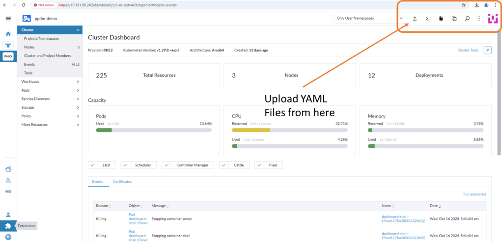
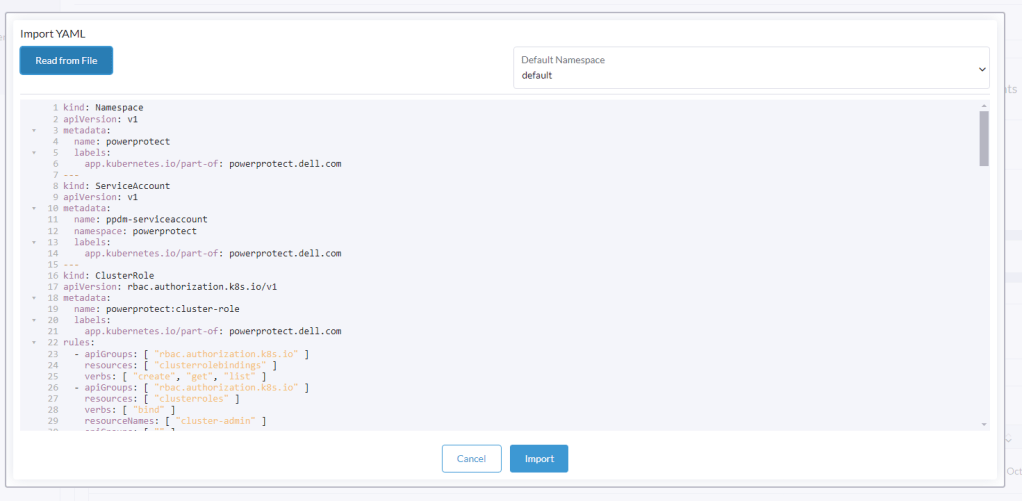
Click ‘Read from File’ and then ‘Import’ the first YAML file (ppdm-controller-rbac) into the default namespace.
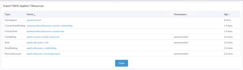
You should get a verification that the cluster was configured with a new Namespace ‘powerprotect’, a new ClusterRole, Service account etc.

Repeat the process for the second YAML you downloaded (ppdm-discovery.yaml)

As you can see this creates another ServiceAccount amongst other entities within the new powerprotect namespace.
1.3 Create the secret for the PPDM-Discovery-ServiceAccount
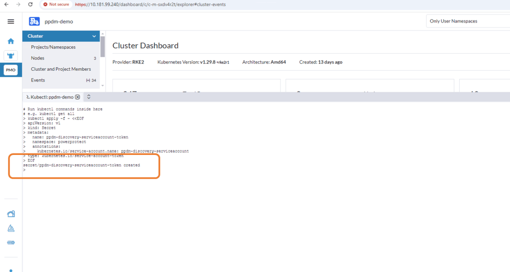
For K8s deployments after 1.24, we need to manually create the secret associated with the service account. Open the Kubectl Shell in Rancher.

Execute the following within the Shell.
kubectl apply -f - <<EOF
apiVersion: v1
kind: Secret
metadata:
  name: ppdm-discovery-serviceaccount-token
  namespace: powerprotect
  annotations:
    kubernetes.io/service-account.name: ppdm-discovery-serviceaccount
type: kubernetes.io/service-account-token
EOF
Once applied you can see that the ppdm-discovery-serviceaccount secret was successfully created.
1.4 Retrieve Secret from the cluster
Using the following command retrieve the secret from the cluster
kubectl -n powerprotect get secret ppdm-discovery-serviceaccount-token -ojsonpath='{.data.token}' | base64 -d -Make a copy of the extracted secret.
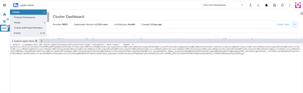
Note:
I have seen on occasion, a situation whereby an additional ‘>’ gets appended as the trailing character of the above output. This will cause the asset discovery process to fail as the secrets won’t match between PPDM and the RKE2 cluster. I have used the following command also and this does not attach the trailing ‘>’
kubectl describe secret $(kubectl get secret -n powerprotect | awk '/disco/{print $1}') -n powerprotect | awk '/token:/{print $2}'
Step 2: Configure Kubernetes Asset Source in PPDM
2.1 Enable Kubernetes Asset Source
Log into PPDM , navigate to the ‘Infrastructure’ tab, then ‘Asset Sources’. Scroll down through the GUI until you see the ‘Kubernetes' tile. Click ‘Enable Source’.

2.2 Configure the Kubernetes Asset Source
Under ‘Asset Sources’, Click ‘Add’. This will guide us through the wizard.

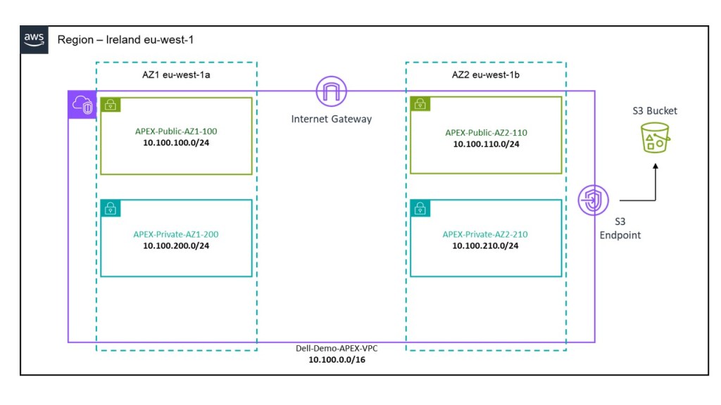
In the next pane, give the Kubernetes cluster a meaningful name, I have chosen the cluster name itself. Note As outlined above I have pointed it to the API interface of the first control plane node. In a production environment this will be the Load Balancer IP address. Also, a much as I harp on about DNS everywhere, I am pointing to a physical IP address and not the FQDN. Leave the discovery port as the default 6443.
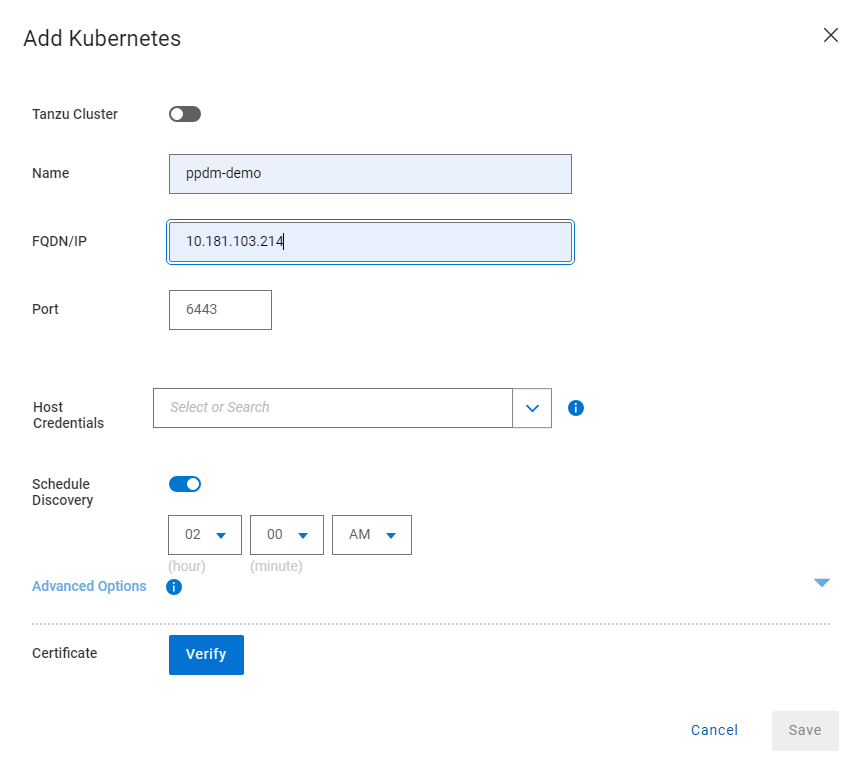
Under the ‘Host Credentials’ field, click the dropdown and ‘Add Credentials’. This is where we will inject the ‘secret’ we extracted form the RKE2 cluster (remember be careful of trailing ‘>’). Give the credential a name ( can be anything) and paste in the Service Account Token. Then click ‘Save’.

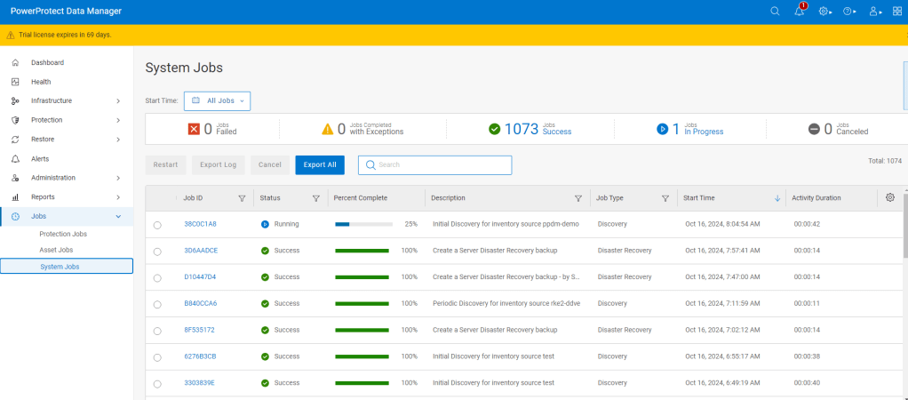
Proceed to ‘Verify’ and ‘Accept’ the certificate and then Save. The asset source should appear in the ‘Asset Sources’ window. Navigating to the System Jobs panel, you will see PPDM undergoing an asset discovery.
Navigate back to the Assets tab and we can see the discovery has completed and we can see all our namespaces in the RKE2 cluster ( including our system namespaces).
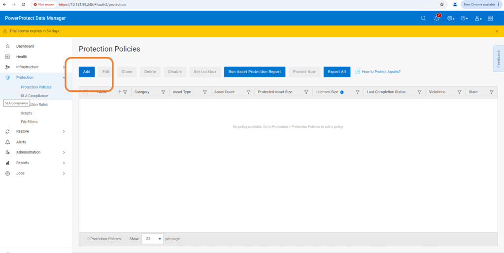
Step 3: Configure Protection Policy for Production Namespace.
Now that we have the end to end infrastructure built, deployed and discovered, we now need to create a policy in PPDM to protect our production application, which resides in the ‘dell-ppdm-demo’ namespace. Lots of screengrabs upcoming, but don’t worry too much if you miss something… it will be in the attached video also.
3.1 Create Protection Policy
This really is a very straightforward process. Navigate to the Protection tab and then ‘Protection Policies’. Click ‘Add’.
Follow the Wizard guided path.
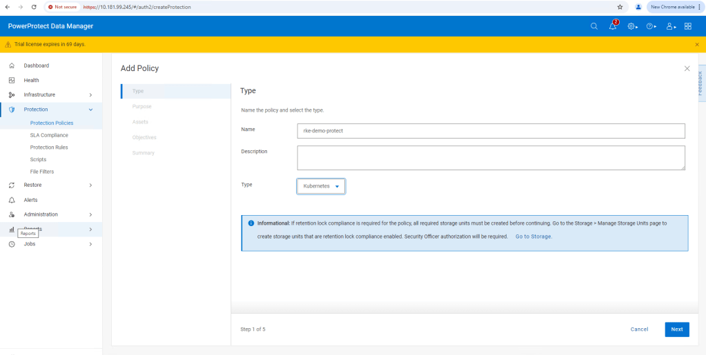
For this demo I am using ‘Crash Consistent’.
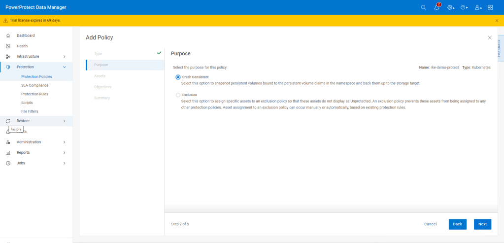
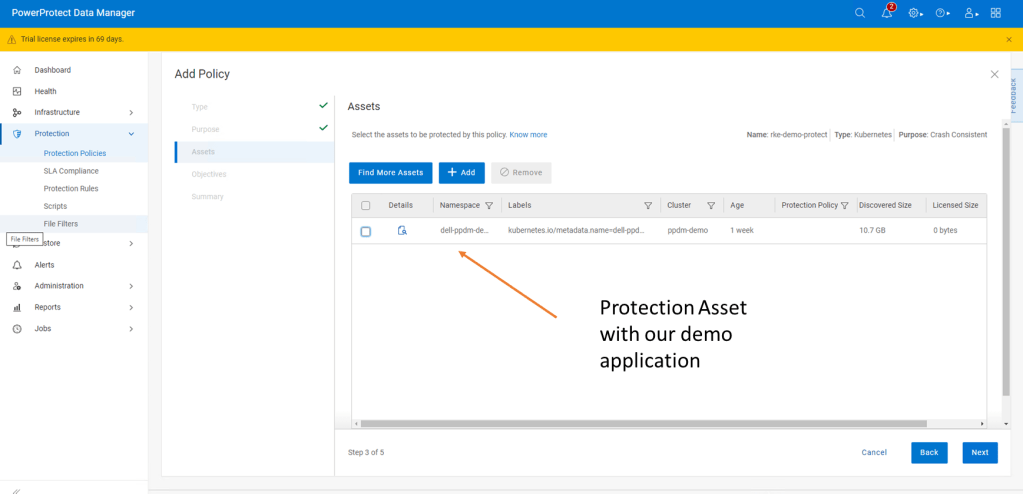
Click next and then add the namespace that contains the application that we have configured. In this case ‘dell-ppdm-demo’.

Next configure our Protection policy objectives, when and where we want to push the backup. Do we want to replicate a secondary copy to the cloud for instance or to a preconfigured cloud tier? For this demo we will keep it simple. We are going to push a ‘Full’ backup to the DDVE instance we have paired with PPDM in the last blog.

Click ‘Add’ under primary backup, and configure the policy parameters. I am going to push a full backup every 1 hour and retain for 1 day, starting at 9 AM and Ending at 9 PM.

Click ‘Next’ and then ‘Finish’.

There you go, this is really incredibly simple. At the next screen, we could wait until the protection policy kicks off as per the schedule but we will cheat a little and run the protection manually ( after the next step!).
Step 4: Configure your Cluster for Snapshot capability
So whilst we have the CSI driver installed on our cluster, we have skipped over one really important step. If we attempt to do a restore or replicate the application to a new namespace ( as we will show in the video), it will fail. The reason being we being we have installed no snapshot capability on the cluster yet.
I have covered this in detail, when we discussed PPDM in an EKS environment. Link to this is here. For now though, follow the following steps.
4.1 Install external CSI Snapshotter
Run the following commands on your cluster using Kubectl.
kubectl apply -f https://raw.githubusercontent.com/kubernetes-csi/external-snapshotter/master/client/config/crd/snapshot.storage.k8s.io_volumesnapshotclasses.yaml
kubectl apply -f https://raw.githubusercontent.com/kubernetes-csi/external-snapshotter/master/client/config/crd/snapshot.storage.k8s.io_volumesnapshotcontents.yaml
kubectl apply -f https://raw.githubusercontent.com/kubernetes-csi/external-snapshotter/master/client/config/crd/snapshot.storage.k8s.io_volumesnapshots.yaml
kubectl apply -f https://raw.githubusercontent.com/kubernetes-csi/external-snapshotter/master/deploy/kubernetes/snapshot-controller/rbac-snapshot-controller.yaml
kubectl apply -f https://raw.githubusercontent.com/kubernetes-csi/external-snapshotter/master/deploy/kubernetes/snapshot-controller/setup-snapshot-controller.yaml
4.2 Confirm the snapshot pods are running
Using the ‘Kubectl get pods -n kube-system‘ command. you should see an output as follows:

4.3 Configure VolumeSnapShot Class
Apply the following YAML to configure the VolumeSnapShot Class
kubectl apply -f - <<EOF
apiVersion: snapshot.storage.k8s.io/v1
kind: VolumeSnapshotClass
metadata:
  name: powerscale-snapclass
driver: csi-isilon.dellemc.com
deletionPolicy: Delete
parameters:
  retentionPolicy: Delete
EOF
Verify it is deployed using the ‘Kubectl get VolumeSnapShotClass‘ command.

Step 5: Test the Protection Policy
Now that we have everything configured properly, we will want to test that the protection policy is functioning. For a scheduled policy we could wait until the scheduled time but for the purposes of the demo we will initiate this manually.
5.1 Invoke ‘Protect Now’
Under Protection Policies, select the protection policy we created earlier. And Click on the ‘Protect Now’ button.

Navigate through the rest of the guided path. On this occasion we will select ‘Full Backup’ versus ‘Synthetic Full’. As it is the first time we have done the backup, technically there will be no difference in any regard.
The Protection Job will kick off and be queued for execution. You can follow its progress via the Jobs tab. All going well, as below, the job should complete successfully.

Step 6: Deploy new namespace from backup.
This will be demonstrated more readily in the video. We will execute a really simple test by:
- Deleting the Namespace ‘Dell-PPDM-DEMO’ and everything in it, including our application. This might simulate a user error for instance.
- Recover the namespace and the application via PPDM
- Log back into our recovered application.
Let’s delete our namespace by using the ‘Kubectl delete ns dell-ppdm-demo‘ command:

Step 6.1 Recover Namespace and application from PPDM
Luckily we have a backup of the namespace. Navigate to the Restore tab in PPDM and select our policy and click ‘Restore’
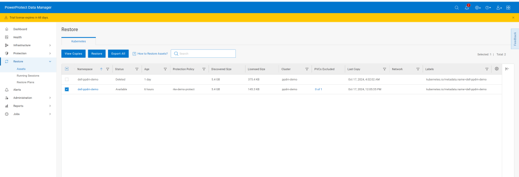
Navigate through the rest of the GUI, its very straightforward. We are going to restore to the original cluster, restore the namespace and associated PVC’s, including all scoped resources. For demo purposes we will restore to newly named namespace called ‘restored-ppdm-demo’.
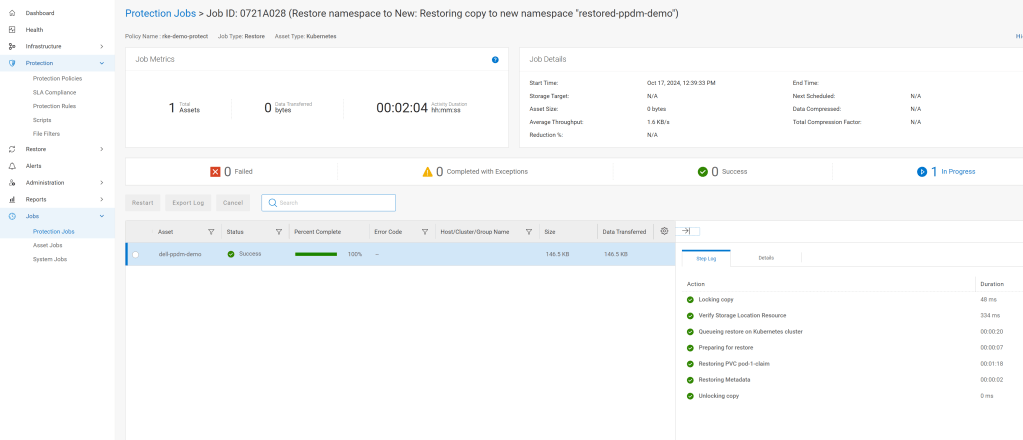
Navigate to the Protection Jobs menu and monitor progress
All going well, dependent on the size of the restore, the operation is a success:
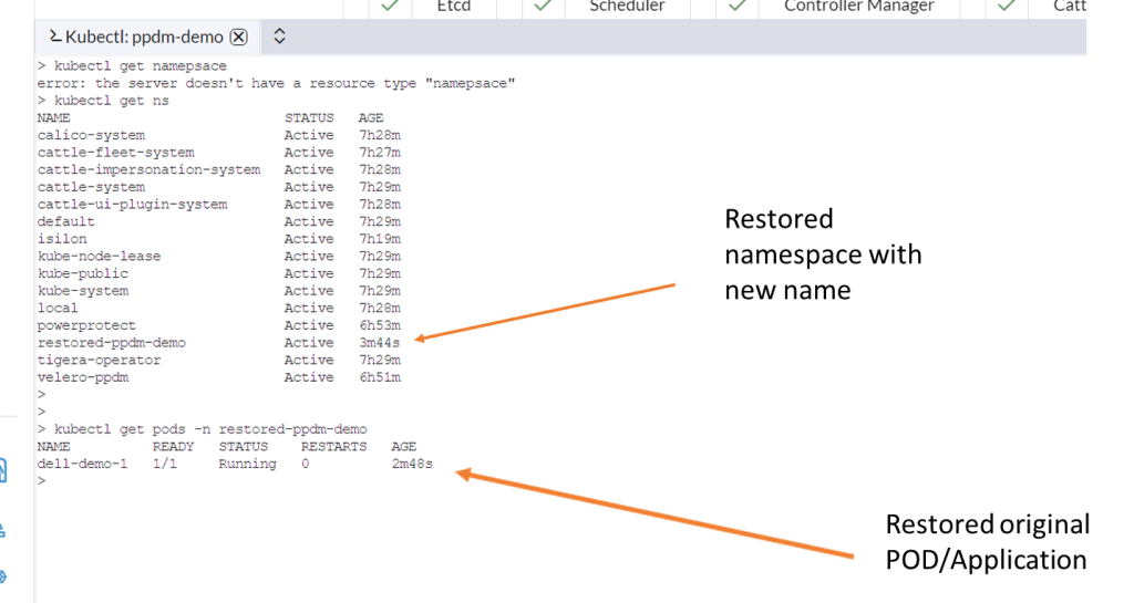
Navigate back to Rancher and lets have a look back in to the cluster to see can we see the restored namespace and associated POD.
Video Demo
DISCLAIMER
The views expressed on this site are strictly my own and do not necessarily reflect the opinions or views of Dell Technologies. Please always check official documentation to verify technical information.
#IWORK4DELL